
- SIGNA MR355 / SIGNA MR360
- Service Manual
- 5856356-3EN Revision 5.0
- Basic Service Documentation. Copyright General Electric Company.
- 00000018WIA3028FD20GYZ
- id_131067955.0
- Feb 21, 2021 9:14:14 PM
1.5T Head Neck Spine (HNS) Mirror Repair/Replacement
Prerequisites
| Required persons | Preliminary requirements | Procedure | Finalization |
|---|---|---|---|
| 1 | Not Applicable | 40 minutes | Not Applicable |
| Item | Quantity | Effectivity | Part number | Manufacturer |
|---|---|---|---|---|
| ⅛” and ¼” Flathead Screwdrivers | 1 each | Replacement of mirror assembly | - | - |
| Item | Quantity | Effectivity | Part number | Manufacturer |
|---|---|---|---|---|
| Mirror assembly FRU | 1 | Replacement of mirror assembly |
2419521 |
GEHC Coils |
About this task
Follow this process to reassemble the mirror assembly.
Procedure
Inspect mirrors to ensure that they are not coming loose from the plastic housings. If the mirrors are coming loose a new mirror assembly will be needed.Notice 
- Inspect all parts for broken snap features. If any of the snap
features are broken, a new mirror assembly will be needed.
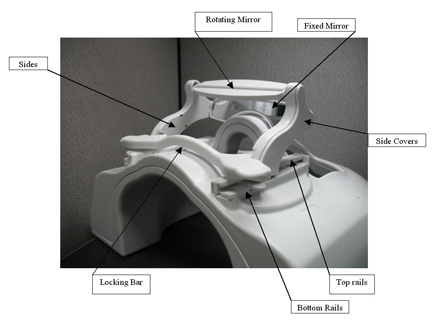
- There are 2 located on each end of each of the cross pieces
(the locking bar, the rotating mirror, and the fixed mirror). See Figure 1.
Figure 1. Cross-Piece Snap Features 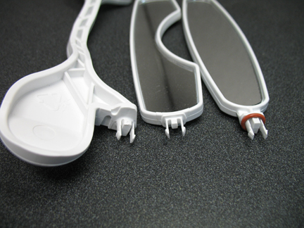
- There are 5 on each of the side covers. See Figure 2.
Figure 2. Snap Features on Side Covers 
- There are 3 on each of the top rails. See Figure 3.
Figure 3. Snap Features on Top Rails 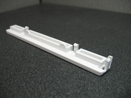
- There are 2 located on each end of each of the cross pieces
(the locking bar, the rotating mirror, and the fixed mirror). See Figure 1.
- If any of the cross pieces have been dislocated from their proper
position (see Figure 4), the side covers will need to
be removed to properly re-seat the snap feature. This is due to the
locking features on the inside of the side covers. The locking features
are the three round features shown in Figure 5.
Figure 4. Cross-Piece Dislocated 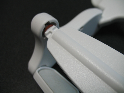
Figure 5. Locking Features on the Side Covers 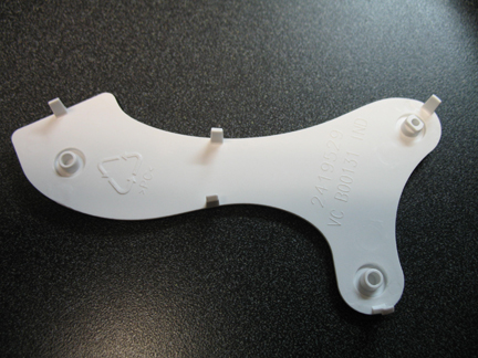
- If needed, the side covers can be removed by inserting a small
screwdriver from the backside of the sides to disengage the snap feature
on the side covers. (See Figure 6.) Start at the bottom and work
up to the top of the mirror.
Figure 6. Removing Side Covers 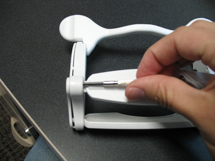
- The rotating mirror requires some additional pressure to properly
engage. This is because of the o-rings, which supply the correct amount
of drag to resist rotation. In the picture shown (see Figure 7), firm pressure is being applied using the thumb and middle finger
while gentle pressure is being applied with the index finger.
Figure 7. Engaging the Rotating Mirror 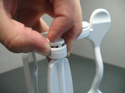
- The reassembly of the rails below is from
the operators manual. To prevent breakage, the mirror is designed
to break away from the anterior face component. In the event that
the mirror assembly is pulled from the anterior face component, the
mirror can be reinstalled using the following procedure:
- Slide the mirror assembly back onto the rails.
Figure 8. Installing Mirror Rails 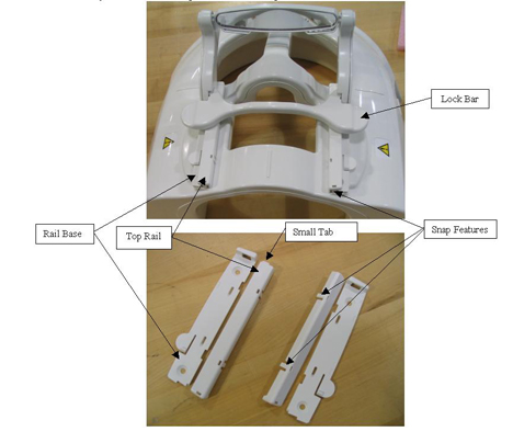
- Slide the mirror assembly back onto the rails.
Finalization
Ensure that all joints are firmly seated and that the mirror assembly is functioning properly.