
- SIGNA MR355 / SIGNA MR360
- Service Manual
- 5856356-3EN Revision 5.0
- Basic Service Documentation. Copyright General Electric Company.
- 00000018WIA3000FF20GYZ
- id_131067855.0
- Feb 21, 2021 9:13:20 PM
1.5T HDx 12CH Body Array - Single Connector Cable Replacements
Prerequisites
| Required persons | Preliminary requirements | Procedure | Finalization |
|---|---|---|---|
| 1 | Not Applicable | 30 minutes | Not Applicable |
| Item | Quantity | Effectivity | Part number | Manufacturer |
|---|---|---|---|---|
| Standard Tool Set | 1 | - | - | - |
| Item | Quantity | Effectivity | Part number | Manufacturer |
|---|---|---|---|---|
| HDx System Cable | 1 | - |
2417328 | - |
| P-connector System Cable FRU | 1 | - |
2424308 | - |
| ||||||||
Cable Removal
Procedure
- Remove the 8 screws from the cover at the pelvic end of the
coil. There are two screws located under the strap. See Figure 1.
Figure 1. Back of Posterior 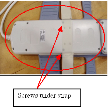
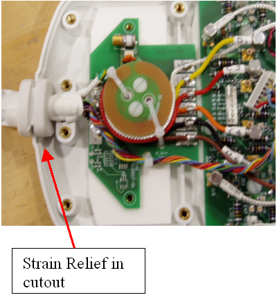
- Unscrew cable clamp. See Figure 2.
Figure 2. Screws at cable clamp 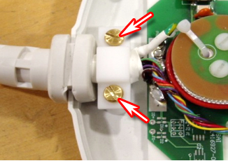
- Locate and disconnect all RF cables coming from the cable trap.
See Figure 3.
Figure 3. Disconnect indicated RF cables 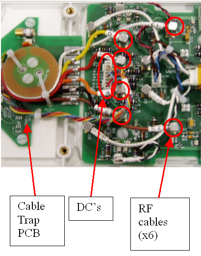
- Remove the cable from the coil. See Figure 4.
Figure 4. Posterior cable removal from coil 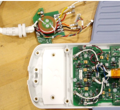
Cable Replacement
Finalization
Finalization
Perform a MCQA test to ensure the coil still operates properly.