
- SIGNA MR355 / SIGNA MR360
- Service Manual
- 5856356-3EN Revision 5.0
- Basic Service Documentation. Copyright General Electric Company.
- 00000018WIA30812F20GYZ
- id_131075763.0
- Aug 29, 2019 1:54:47 AM
1.5T HD Shoulder Array Cable Replacement
Prerequisites
| Required persons | Preliminary requirements | Procedure | Finalization |
|---|---|---|---|
| 1 | 0 minutes | 30 minutes | 0 minutes |
| Item | Quantity | Effectivity | Part number | Manufacturer |
|---|---|---|---|---|
| Screw Driver Set | 1 | - | - | - |
| Item | Quantity | Effectivity | Part number | Manufacturer |
|---|---|---|---|---|
| 2417165: 1.5T HD Shoulder Array Cable | 1 | - | - | - |
About this task
Follow this process to replace the cable assembly on the 1.5T HD Shoulder Array by GE/USAI (M3335MN).
| Last Update | 01/05/2006 |
Procedure
- Remove the cover from the shoulder coil
Figure 1. Remove the cover 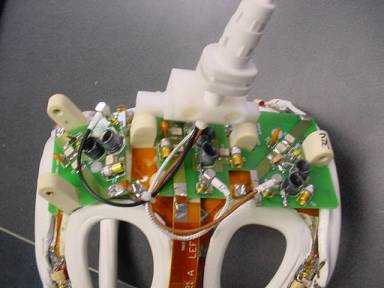
- Remove the two screws that hold the cable clamp in position (cable is
captured beneath).
Figure 2. Ttwo screws that hold the cable clamp 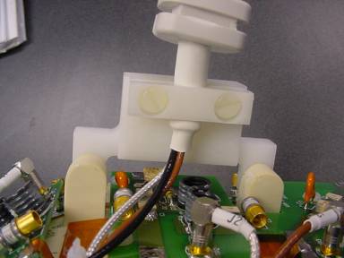
- Install the covers and replace the screws removed in Step 1. Make sure
to capture the strain relief inside of the covers.
Figure 3. Install the covers 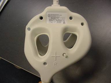
Finalization
No finalization steps.