
- SIGNA MR355 / SIGNA MR360
- Service Manual
- 5856356-3EN Revision 5.0
- Basic Service Documentation. Copyright General Electric Company.
- 00000018WIA30CE1F20GYZ
- id_131067283.0
- Aug 29, 2019 1:54:36 AM
1.5T HD 8Ch High Res Brain Array Coil Replacements
Prerequisites
| Required persons | Preliminary requirements | Procedure | Finalization |
|---|---|---|---|
| 1 | 0 minutes | 30 minutes | 0 minutes |
| Item | Quantity | Effectivity | Part number | Manufacturer |
|---|---|---|---|---|
| ¼ inch flat blade screwdriver | 1 | - | - | - |
| Item | Quantity | Effectivity | Part number | Manufacturer |
|---|---|---|---|---|
| Refer to FRU Document | NA | - | - | - |
| ||||
About this task
Follow this process to replace field replaceable units for the 1.5T HD 8 Channel High Res Brain Array by Invivo. (M3335LZ)
Cable Replacement
Cable Continuity Check
Procedure
Cable Replacement Procedure
Procedure
- The 4 coil connector mounting screws are located at the superior
end of the coil. Remove the 4 coil connector mounting screws as detailed
in illustration1.
Figure 1. Remove four screws 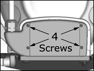
Mechanical Parts Replacement
Mechanical Hardware Check
About this task
Lift the coil latches on both sides of the coil, and slide the coil to its superior and inferior extents. The coil must slide freely on the base with no binding or grinding. Make sure that the coil does not move with respect to the baseplate when the latches are locked down.
Procedure
Replacement of Inferior or Superior Mirror
About this task
There are two mirrors included with the 1.5T HD 8 Channel High Res Brain Array: To install either mirror, align the grooves in the base of the mirror with the grooves in the coil mirror mount, and slide the mirror into position. Press and hold the release button on the mirror before attempting to remove the mirror.
-
Superior Mirror
-
Inferior Mirror
Figure 2. Superior Mirror 
Figure 3. Inferior Mirror 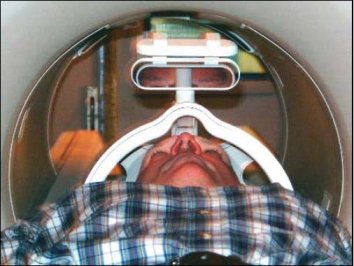
Procedure
Replacing the Mount Plate Assembly
Procedure
- Lift the coil latches on both sides of the coil, and slide the
coil to its superior extent.
Press on the coil release button on the base plate.
Slide the coil complete off the baseplate
Figure 4. Release button 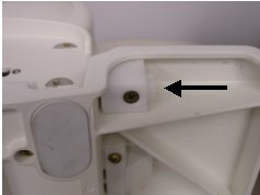
- Remove the screws (eight) .
Figure 5. Mount plate screws 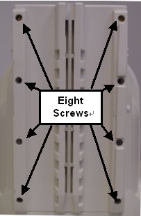
Replacing the Spring Foam
Procedure
- Remove the screw from the release button assembly .
Figure 6. Release Button Assembly 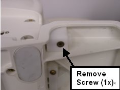
- Remove the slider from the release button mounting block .
Figure 7. Remove Slider 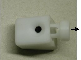
- Remove and replace the spring foam. Note:
There are 2 spring foams in each Spring foam FRU set. Place the slider with the new spring foams back in to the mounting block Attach the mounting block back to the baseplate using the screw removed in step 1
Figure 8. Replace Spring foams 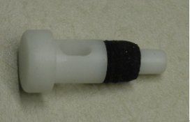
What to do next
Finalization
No finalization steps.