
- SIGNA MR355 / SIGNA MR360
- Service Manual
- 5856356-3EN Revision 5.0
- Basic Service Documentation. Copyright General Electric Company.
- 00000018WIA30A8DF20GYZ
- id_131060423.0
- Aug 29, 2019 1:55:40 AM
1.5T Express Coil: 9E Anterior Array Cable Replacement
Prerequisites
| Required persons | Preliminary requirements | Procedure | Finalization |
|---|---|---|---|
| 1 | 0 minutes | 30 minutes | 0 minutes |
| Item | Quantity | Effectivity | Part number | Manufacturer |
|---|---|---|---|---|
| Standard Tool Set | 1 | - | - | - |
| ||||
Cable Removal
Procedure
- Remove all 20 screws from the cover as shown in the Figure 1 and retain them safely.
Figure 1. 20 screws 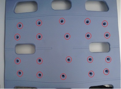
- Unscrew cable clamp. See Figure 2.
Figure 2. Unscrew cable cramp 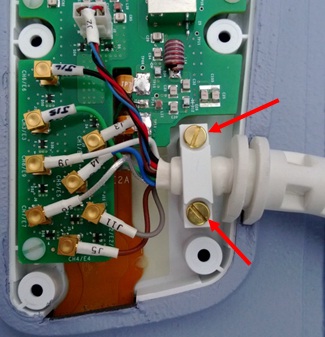
- Locate and disconnect all 8 RF cables and 1 DC cable (J2) coming
from the cable assembly. See Figure 3
Figure 3. RF Cable and DC Wire Removal 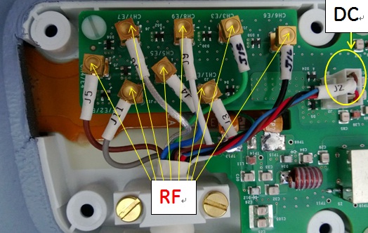
- Remove the cable from the coil. See Figure 4.
Figure 4. Cable Removal 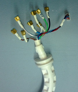
Cable Installation
Procedure
- Place strain relief in cut-out as shown in Illustration 5.
Figure 5. strain relief 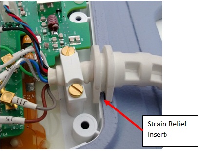
- Secure cable clamp over cable until tight with the previously
removed brass screws.
Figure 6. brass screws 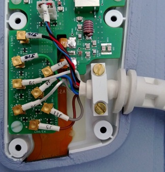
- Connect the RF Co-axial connectors labeled with J3, J11, J15,
J5, J4, J16, J6, and J9 to matching (labeling) RF connectors on PCB
as shown in Illustration 7.
Figure 7. RF Coaxial Connector and DC wires 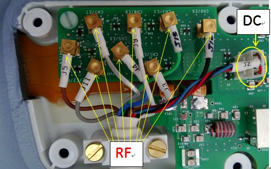
Finalization
Procedure
Perform Express Coil MCQA Test.