
- SIGNA MR355 / SIGNA MR360
- Service Manual
- 5856356-3EN Revision 5.0
- Basic Service Documentation. Copyright General Electric Company.
- 00000018WIA30DDBF20GYZ
- id_131070061.3
- Jul 6, 2019 12:17:32 AM
MCR III Chain Tool Troubleshooting for Optima MR360 / Brivo MR355
| Required persons | Preliminary requirements | Procedure | Finalization |
|---|---|---|---|
| 1 | Not Applicable | Not Applicable | Not Applicable |
| ||||
Failures after Running Port A Default Tests
- If you find errors after running the default tests (see MCR III Tool) refer to Table 3 to determine your response:
Table 3. Default Test Troubleshooting Failure Response Port A with Preamps OFF test and Uno sub-tests • Preamp Status (OFF) This validation will not be performed when preamps are off • Excess Noise (OFF) This validation will not be performed when preamps are off • Dead Channel (OFF) If Dead Channel (ON) validation for the same channel passed, replace Multicoil Interface Box If Dead Channel (ON) validation for the same channel also failed, see fault isolation procedures • Low Signal (OFF) Run Mega Switch OSC Test • Ch-Ch Variance (OFF) Review validation results (see Note below) Port A with Preamps ON test • Preamp Failed (ON) Replace Multicoil Interface Box • Excess Noise (ON) Replace Multicoil Interface Box • Dead Channel (ON) If Dead Channel (OFF) validation for the same channel passed passed, replace Multicoil Interface Box If Dead Channel (OFF) validation for the same channel also failed, see fault isolation procedures • Low Signal (ON) Run Mega Switch OSC Test • Ch-Ch Variance (ON) Review validation results (see Note below) Note: Channel to Channel Variance Failure This test fails when channel values are not within set tolerances. Because tolerances are fairly loose, there is no way to objectively isolate the failure point/cause. In order to determine which channel may be problematic, view the channel output values in the test results and look for some value whose variance is dissimilar to the others.
Isolating Port A Failures
Port A: Dead Channel Failure: If the ON and OFF versions of the Dead Channel tests of any singular channel has opposite results (for example the Dead Channel (OFF) test for Channel 2 fails but the Dead Channel (ON) test for Channel 2 passes), the Multicoil Interface Box should be replaced. If the Dead Channel tests for ON and OFF both failed, perform the following.
- On the back of the MIB (see Figure 1) identify the cables from the channel that failed the Dead Channel
test and a cable from any channel that passed the Dead Channel test.
Figure 1. Multi-coil Interface Box (MIB) Rear Location 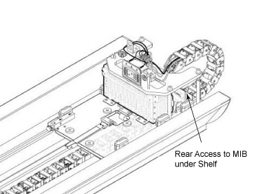
- On the upper level, swap the passing channel with the failing
channel (see Figure 2), and then re-run the Port A test.
Figure 2. MIB Channels 1-8 IN (J1-8) 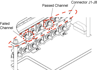
If the problem moved to previously passing channel, replace the cable segment between Port A and the MIB. Return cables to their original positions.
If the problem remains on the same channel, return cables to their original positions and proceed to 3.
- On the lower level, swap the passing channel with the failing
channel (see Figure 3), and then re-run the Port A test.
Figure 3. MIB Channels 1-8 OUT (J9-16) 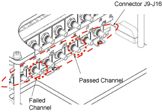
If the problem moved to the previously passing channel, replace the cable segment between the MIB and the Mega Switch. Return cables to their original positions.
If the problem remains on the same channel, return cables to their original positions. You need to replace the Multicoil Interface Box.
Isolating express PA Coil Test Failures
- If you find errors after running the express PA coil - cradle
test (see MCR III Tool for SV 1.5T), the test result Figure 4 is shown. In this case, please follow from 2.
Figure 4. Example of Fail Result 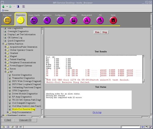
- If failed in test, please try re-connect cable connector again and test again.
- If it's still failed, connect MCR Tool to convert board at Dock
and run diagnostic program for express coil again as follows.
- Remove cover 1, 2 at dock area.
Figure 5. Remove Covers 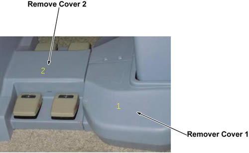
- Remove DC cable ASSY _5346920 and RF cable ASSY_5346919 from
convert board at dock.
Figure 6. Remove Cables 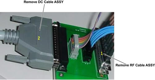
- Connect those 2 cable to MCR3 Tool, Then run diagnostic program
for express PA coil-Dock
Figure 7. Connect Cables 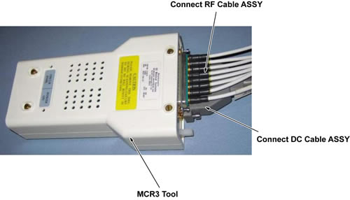
- If passed, replace cable ASSY in Cable Track.
- If failed, replace cable ASSY from Mega Switch to Dock.
- Remove cover 1, 2 at dock area.
- Restore the cables of PA Coil or Convert Board at Dock.
Finalization
No finalization steps.