
- SIGNA MR355 / SIGNA MR360
- Service Manual
- 5856356-3EN Revision 5.0
- Basic Service Documentation. Copyright General Electric Company.
- 00000018WIA303D1F20GYZ
- id_131075901.1
- Jul 5, 2019 10:46:05 PM
1.5TGP Flex Coil Troubleshooting Tips
Overview
The following tips can be used to troubleshoot common problems with the Signa Horizon 1.5T /Signa Horizon LX 1.5T /Signa Twin Speed 1.5T/Signa Infinity 1.5T Signa Infinity Twin Speed 1.5T/Signa CV/i 1.5T/Signa MR/i 1.5T /Signa HDe 1.5T GP Flex coil.
Coil fault Troubleshooting
The system reports a coil fault during prescan or does not recognize the coil connection to the system when selected in the software
| Probable Cause | Suggested Actions | Resolution |
| The coil connector has become disconnected from the system interface. | Check to make sure the coil connector is fully engaged. | Engage connector and try the scan again. |
| Coil ID issues. | From CSD, select Diagnostics, Manual Tests, SRI Functional Checks, and run the SRI Coil ID test. Compare the coil ID value found to that listed in the coil configuration. | If the value does not match, or no coil ID is found, perform Cable Replacement. |
External Cable Check
-
Select the DIODE TEST function on the DMM.
-
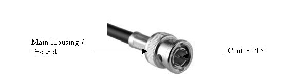
Connect the POSITIVE lead of the DMM to the center pin of the BNC on the external cable. Connect the NEGATIVE lead to the main housing/ground of the BNC.
-
Flex the external cable, especially near the connectors and the strain relief, and observe that a reading of 0.400 to 0.600 should remain on the DMM, with no instability or fluctuations.
-
Connect the POSITIVE lead of the DMM to the main housing/ground of the BNC on the external cable. Connect the NEGATIVE lead to the center pin of the BNC.
-
Flex the external cable, especially near the connectors and the strain relief, and observe that a reading of INFINITY should remain on the DMM, with no instability or fluctuations.
-
If the cable fails any of the above tests, replace it. Refer to Section 5-2 External Cable Replacement.
PIN Diodes Check
There is only one PIN diode in this antenna. This procedure will indicate if the PIN diode is defective.
-
Select the DIODE TEST function on the Digital Multimeter (DMM).
-
Connect the POSITIVE lead of the DMM to the center pin of the BNC on the external cable. Connect the NEGATIVE lead to the main housing/ground of the BNC.
-
A reading of 0.400 to 0.600 should be observed on the DMM.
-
If a reading below 0.400 is observed in either direction, either the output cable is shorted or the PIN diode is bad.
-
If a reading above 0.600 is observed in step 3, the PIN diode is defective.
-
Connect the POSITIVE lead of the DMM to the main housing/ground of the BNC on the external cable. Connect the NEGATIVE lead to the center pin of the BNC.
-
A reading of INFINITY should be observed on the DMM.
-
If a reading of INFINITY is observed in both directions, either the output cable is open or the PIN diode is open.
-
If any of the above conditions fails, replace the PIN diode. Refer to Section 5-4 Replacing the PIN Diode.