
- SIGNA MR355 / SIGNA MR360
- Service Manual
- 5856356-3EN Revision 5.0
- Basic Service Documentation. Copyright General Electric Company.
- 00000018WIA30570110GYZ
- id_20033079.7
- Jul 4, 2021 10:39:24 PM
System and hardware configuration
This topic describes the values and explanation of each parameter for system configuration and hardware configuration in Guided Install.
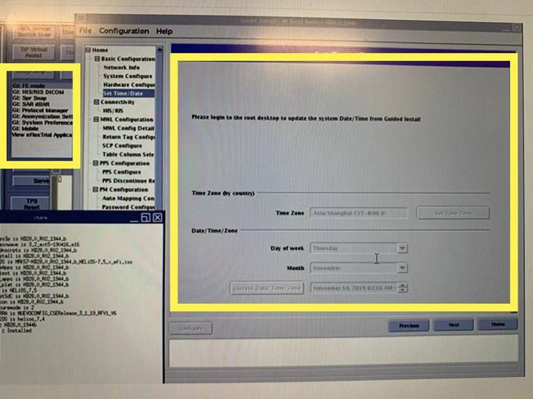
The MR System is configured for the various hardware interactions within the system using the Guided Install System Configure and Hardware Configure tabs.
Below are the examples of the System Configure and Hardware Configure tabs, respectively (these are only examples and are subject to change based on software revision).
The following table provides guidance to fill out the various system configuration parameters.
| System configuration | ||
|---|---|---|
| Parameter | Explanation | Value |
| Hospital Name | Enter the name of the hospital or site that will appear at the top of filmed images. | Site-entered |
| Suite_ID | Enter the name of the suite to which the scanner will be connected. If the system is connected to a suite of systems, the name may need to be acquired from the site's system administrator. If the system is stand-alone (not connected to a suite or hospital network), the name is at the option of the installer. | Site-entered |
| Host_ID | Enter the name of the system host. If the system is connected to the site's network, the name may need to be acquired from the site's system administrator. If the system is a stand-alone (not connected to a suite or hospital network), the name is at the option of the installer. | Site-entered |
| Unique / System ID | This is the GE CARES Unique system ID. This information is generated through the GEMS local area service manager. A dummy ID can be entered if the correct ID is unknown to speed up installation. The installer can go back and update this field with the correct code later when the correct information is known. An example of a dummy ID could be 123. | Site-entered |
| Service ID | This is the GE CARES System ID. This information is generated through the GEMS local area service manager. A dummy ID can be entered if the correct ID is unknown to speed up installation. The installer can go back and update this field with the correct code later when the correct information is known. An example of a dummy ID could be 123. However it should be noted that the entire GE back office connectivity suite, including Remote Software Download (RSD), is highly dependent on this entry being accurate. | Site-entered |
| Date Format | This is the date structure to be used/displayed by the system. A choice of one of six options are available. Each with date format and standard time (AM/PM) or military time (24 hour clock). Japanese ERA time format is also provided. | (MMM DD YY AM/PM) [(MMM DD YY AM/PM), (DD MMM YY AM/PM), (YY MMM DD AM/PM), (MMM DD YY 0-23), (DD MMM YY 0-23), (YY MMM DD 0-23)] |
| Weight Unit | Select the unit of measurement desired by the site's staff: kilograms or pounds. | Pounds (Pounds, Kilograms) |
| Keyboard | Choose the keyboard language that will be used for this system. | American (American, French, German, Italian, Portuguese, Spanish, Swedish, Danish, Dutch, Norwegian, Finnish) |
| Language | Choose the language that will be used where the system is being installed. | English (English, French, German, Italian, Portuguese, Spanish, Japanese, Chinese, Danish, Dutch, Norwegian, Finnish, Swedish) |
| Video Card | Video card value is selected automatically. | N/A |
| Display Type | LCD Monitor - Other is selected as default. | LCD Monitor - Other |
| Legacy Image Type | Legacy Image Type: Select the legacy image type for the system being installed: Yes, No. | Yes (Yes, No) |
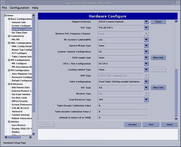
The following table provides guidance to fill out the various hardware configuration parameters.
The Guided Install Product Based Selection feature lets you select the product that you are installing during the Load From Cold procedure. The fields in the Guided Install hardware tab are automatically populated based on the product that you select.
| Parameter | Explanation | Value |
|---|---|---|
| Product Name | Select the product name for the product being installed. |
1.5T,1.5T, 60cm, SIGNATM MR355/MR360 |
| Field Strength | - | 1.5T |
| Package Name | Gradient drivercoil package name. | XFD |
| Gradient Type | Gradient driver type. | 8919(XFD) |
| Resonance Module | Gradient coil type. | BRM |
| Magnet Serial Number | Enter the magnet serial number for the installed system. The serial number can be found on the rating plate on the magnet. |
R RD CR RE |
| Magnet Ramp Direction | - | Forward |
| Table Limit | - | Autopopulated |
| Scan Range | Long is the default value. Select Short if there is not enough room for the cable overhang between the rear ped and the customer wall. | Short |
| Line Frequency |
Select the incoming power line frequency under which the installed site will operate. Selections are: 50 Hz 60 Hz |
60 Hz 50 Hz |
| RF Amp Type | - | 1.5T CSA RF amp |
| Governing Body |
Select the governing body according to the Region rule. Selections are: iec MHLWJIS fda2 special1 special2 | fda2, iec, MHLWJIS, special1, special2 |
| ISO Vector Z | Enclosure and IsoZ value. | 9600 Magnet Enclosure |
| Magnet Enclosure | - |
SIGNA Creator/ Explorer |
| PAC Type | - | PAC2B/PAC5 |
| RFSystems Cabinet (RFS) | Yes is the default value. | Yes |
| Spectro RF Amp Type |
None is the default value. For a site that has an MNS option, select a valid MNS option. | None |
| Scanner Channel Configuration |
Select the channel configuration as applicable. Note: Some channel configurations may require option keys.
| 16 |
| Shim Supply Type |
None is the default value. Select NAV Shim Supply/ RRI Shim Supply if have | None |
| LPCA/Port Configuration | - | SV LPCA |
| Cooling Cabinet Type |
None is the default value. Check the part number of the HEC at the site and configure. To identify the HEC type. | None |
| UPM Type | - | QUPM 1MHz sampling rate |
| Table Configuration | - |
Detectable Table Fixed Table 160.0kg weight limitation Fixed Table 200.0kg weight limitation |
| SSC Type | - | ICE |
| Receiver Type | - | RRx |
| Grad Processor type | - | GP4 |
| Table Encoder Calibration Value | - | None |
| Altitude in Meters |
The altitude of the installation site determined using a website. To determine the altitude, see: Allocations: https://elevationmap.net/. United States locations: https://viewer.nationalmap.gov/advanced viewer/. | Altitude entry not needed |