
- SIGNA MR355 / SIGNA MR360
- Service Manual
- 5856356-3EN Revision 5.0
- Basic Service Documentation. Copyright General Electric Company.
- 00000018WIA30CDCF20GYZ
- id_131070531.1
- Jul 6, 2019 12:03:28 AM
TNS DP
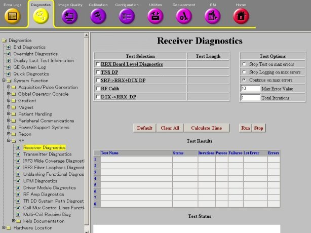
Diagnostic Link
Diagnostics >> System Function >> RF >> Receiver Diagnostics
Diagnostics >> Hardware Location >> Magnet Room >> Receiver Diagnostics
Purpose
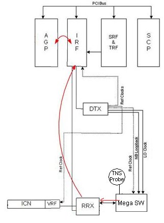
The TNS Datapath Diagnostic tests the Transient Noise Suppression (TNS) related connection between the RRX modules and the TNS circuit in Mega SW. It also tests the TNS circuit’s ability to detect and signal transient noise (spikes). The first RRX module controls the TNS circuitry in the TDM circuit. When the MegaSwitch detects a spike event, it sends a notch signal to each RRX module. The RRX module responds by using analog and digital mechanisms to suppress the spike signal in the sampled data sent to the ICNs.
Components Tested
-
TNS circuit in Mega SW
-
RRX to Mega SWcables
-
TNS control circuits in the RRX modules
Requirements
Run and pass the RRX BLD before running the TNS DP.
Block Diagrams
Test Sequence
-
The RRX module sets up a condition for the MegaSwitch to detect constant spike events and verify that each RRX module has notched out all of its data.
-
The RRX module sets up a condition for the MegaSwitch to NOT detect constant spike events and verify that each RRX module DOES NOT notch any data.
-
RRX’s ability to count notch events and to use analog only and digital only means to notch data.
Expected Results
Output values are judged pass or fail. In the event of failure, the details of the failure can be found in the GE System Log.