
- SIGNA MR355 / SIGNA MR360
- Service Manual
- 5856356-3EN Revision 5.0
- Basic Service Documentation. Copyright General Electric Company.
- 00000018WIA30B3CF20GYZ
- id_131070541.1
- Jul 6, 2019 12:03:29 AM
RF Calibration DP
Diagnostic Link
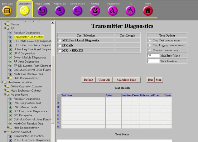
Diagnostics >> System Function >> RF >> Transmitter Diagnostics
Diagnostics >> System Function >> RF >> Receiver Diagnostics
Diagnostics >> Hardware Location >> System Cabinet >> Transmitter Diagnostics
Diagnostics >> Hardware Location >> Magnet Room >> Receiver Diagnostics
Purpose
The RF Calibration DP diagnostic performs and tests the following calibrations: The Transmit Gain (TG) calibration for the narrowband and broadband exciters (DTX), the DC offset adjustments for the RRX modules, and the R1 Gain measurements for the switch boards in the Mega SW. All of these calibrations are performed each time the system is TPS reset. The RF Calibration DP re-runs the same calibrations but adds some addition tests that are too time consuming to run during TPS reset.
During the DC offset adjustment of the RRX channels, the RRX input channels are blanked and then the A to D converters are adjusted until there is no DC offset. This calibration can fail if excessive DC bias is found in any channel. This calibration generates the log file /usr/g/service/log/rrxZeroOffset_<date>.log The log contains the offset value required to zero each channel. Any RRX module that fails this calibration must be replaced.
The Transmit Gain (TG) calibration generates a table of data for each exciter needed to set the DTX’s output attenuator to any point from 0.0db to 39.9dB in 0.1dB steps. The attenuator circuit in DTX-1 has a coarse and fine control. The TG calibration determines the correct coarse and fine setting needed to achieve each of the 400 TG points that can be commanded during a scan. The results of the DTX-1 TG calibration are saved to the log file /usr/g/service/dtx1_cal_I_<date>.log
The TG calibration is followed by a TG validation. During validation, the exciter output level is measured at each of the 400 pre-calculated points and verified to be within 0.1dB of the intended signal strength. An inaccurate TG table will result in poor control of flip angle during a scan. The results of the DTX-1 TG validation are saved to the log file /usr/g/service/dtx1_val_I_<date>.log
The R1 Gain calibration measures the 13 R1 gain steps for the switch boards in the Mega SW. The measured gains must be within the specifications for those boards for this calibration to pass. The difference in gain between channels for each R1 step must also be within specification. During this calibration, the DTX1 output is sent to the Mega SW control board which sends the signal through each channel of each switch board. The DTX-1 signal is left alone while the R1 gain steps in the switch boards are changed. The results of this calibration are saved in the log file/usr/g/service/log/r1GainCal_<date>.dat
Components Tested
-
RRX
-
MegaSwitch
-
DTX (Exciter)
Requirements
Run and pass the IRF3 BLD, DTX BLD, and RRX BLD.
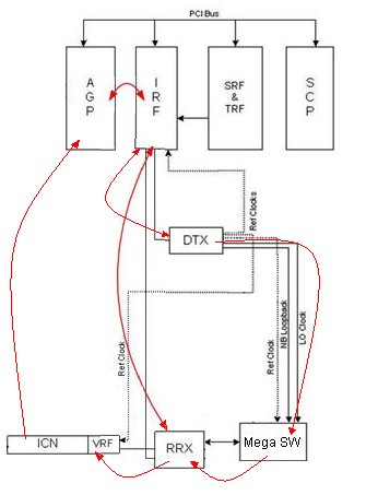
Block Diagrams
Test Sequence
-
Select the RF Calibration DP test.
-
Click Run.
-
Ensure that the diagnostic passes by reviewing the status in the Test Results table.
Expected Results
This diagnostic has either a passed or failed status. If the diagnostic has failed, please review the error log and corresponding extended error message for subsequent actions.
In the event that the diagnostic reports a timeout, the diagnostic may not have been executed. Retry the test. If it continues to time out, complete a TPS Reset and then retry the test.