
- SIGNA MR355 / SIGNA MR360
- Service Manual
- 5856356-3EN Revision 5.0
- Basic Service Documentation. Copyright General Electric Company.
- 00000018WIA30AC1F20GYZ
- id_131075881.1
- Jul 6, 2019 12:03:29 AM
1.5TGP Flex Coil Replacements
Overview
Follow this process to replace the external cable and mechanical hardware of Signa Horizon 1.5T /Signa Horizon LX 1.5T /Signa Twin Speed 1.5T/Signa Infinity 1.5T/ Signa Infinity Twin Speed 1.5T/Signa CV/i 1.5T/Signa MR/i 1.5T /Signa HDe 1.5T GP Flex coil.l
Procedure
Simple removals that are clearly obvious are not described here.
Unless otherwise noted, the steps for re-assembly are simply the reverse order of the steps described for disassembly.
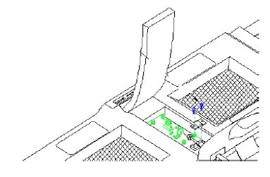
Assembly/ Disassembly of Coil
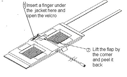
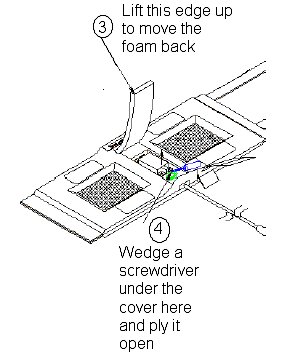
To re-assemble put the cover back on the posts and press on it till it snaps back into place. Push the foam flap under the jacket. Carefully put the fabric flap into place making sure that the Velcro on the edges lines up with the Velcro on the jacket. Tuck the end of the flap under the jacket. Press over the Velcro while making sure that no edges are left open.
External Cable Replacement
-
Disassemble the coil as per Section 4-1 Disassembly/ Assembly of Coil. Unscrew the two nylon screws and remove the strain relief upper cover
-
Unscrew (use two 8mm wrenches, one on the circuit board female connector and one on the male cable connector) and remove the male SMA cable connector from the circuit board. Be careful not to twist the female SMA connector from the circuit board.
-
Put the external cable out of the coil.
-
Install the new cable. Stabilize the circuit board and the connector on the circuit board. Too much torque (>8inch-lbs) can cause damage.
-
Put the strain relief back on. Reassemble the coils as per section 4-1 Disassembly/ Assembly of GP Flex Coil
Mechanical Hardware Replacement
-
Refer to FRU Document for the hardware kit part number
-
To replace the cover assembly refer to Section 4-1 Disassembly/Assembly of Coil.
-
To replace the upper strain relief block and the two screws refer to Section 4-2 Replacing the External Cable.
-
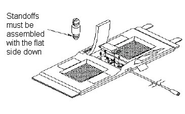
If a plastic standoff breaks it can be pulled out using a needle nose plier. Insert a new standoff in its place while making sure that the flat end goes in first. See Illustration given below.
Replacing the PIN Diode
Antenna is tuned at the factory to provide the proper input impedance. Circuit board is not field replaceable. PIN diode is the only field replaceable component on the circuit board.
-
Disassemble the coil as per section 4-1 Disassembly/Assembly of GP Flex Coil
-
Use an antistatic wristband when touching the circuit board
-
Replace the PIN diode only with an exact replacement diode. (See FRU Document).
-
Reassemble the coil as per Assembly/ Disassembly of Coil Disassembly/ Assembly of GP Flex Coil