- id_13106272
- Version: 3.0
- Date: Aug 29, 2019 1:58:15 AM
GEM RT Open Array Replacement
Prerequisites
| Required persons | Preliminary requirements | Procedure | Finalization |
|---|---|---|---|
| 1 | Not Applicable | 30 minutes | Not Applicable |
| Item | Quantity | Effectivity | Part number | Manufacturer |
|---|---|---|---|---|
| Flathead screwdriver | 1 | - | - | - |
| Side cutters | 1 | - | - | - |
| Item | Quantity | Effectivity | Part number | Manufacturer |
|---|---|---|---|---|
| FRU, GEM RT open array | 1 | - |
See FRU Manual |
- |
| FRU, GEM RT open array system cable | 1 | - |
See FRU manual |
- |
| 100G shock sensor | 1 | - |
See FRU manual |
- |
This document provides instructions to remove the system cable for the GEM RT Open Array coil for both 1.5T and 3.0T magnets.
Procedure
- notice
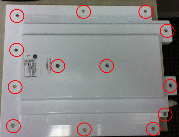
- Locate the bottom of the coil and remove all screws. Remove
the cover.
Figure 1. Screw Locations on Bottom of Coil
- Remove the cable ties with side cutters.
Figure 2. Cable Tie and Connector Locations
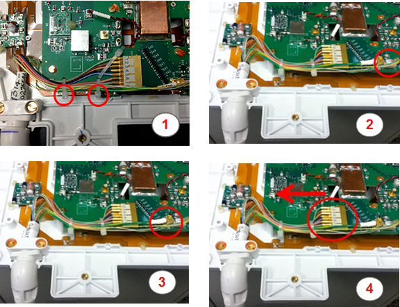
Item Description 1 Location of cable ties 2 J37 connector 3 J38 connector 4 J39 connector - Remove the J37 connector. Push the tab on the side in to release the connector and pull straight up.
- Remove the J38 connector by pulling straight up.
- Remove the J39 connector.
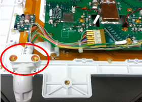
- Remove the cable clamp and screws.
Figure 3. Screws Holding Cable Clamp
 caution
- Replace the coil FRU or cable FRU.
As you replace the cables, carefully route the cable in the notch of the PCB assembly.
Figure 4. Routing Cable on PCB Assembly
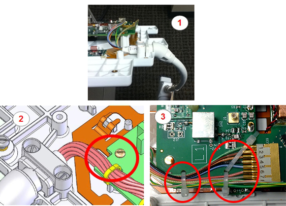
Item Description 1 Orientation of the cable 2 Notch in PCB assembly and screw 3 Placement of the cable ties - Perform the steps in this procedure in reverse order to reinstall the system cable.
 |
 |
Finalization
Proceed to GEM RT Open Array MCQA Setup, and run Multi-Coil Quality Assurance Tool to verify that the coil operates properly.