- id_13106001
- Version: 4.1
- Date: Nov 7, 2019 2:37:56 PM
Anterior Array (AA) FRU and replacement
AA FRU
| Item | Description | GE Part Number |
| 1 | FRU, 3T Anterior Array (AA) coil | 5850201 |
| 2 | FRU, Kizuna Anterior Array (AA) Long Cable | 5543532 |
| 3 | FRU, Anterior Array (AA) Asset Imaging Pad | 5504503 |
| 4 | FRU, Anterior Array (AA) Coil Positioner | 5408174 |
| 5 | FRU, Anterior Array (AA) Strap Kit | 5503457 |
AA cable replacement
Follow this procedure to replace the system cable on the AA Coil. Before beginning this procedure, remove the coil from the magnet room. Wear an ESD wrist strap to avoid electrostatic discharge.
Personnel requirements
| Required persons | Preliminary requirements | Procedure | Finalization |
|---|---|---|---|
| 1 | 45 minutes |
Preliminary requirements
Tools and test equipment
| Item | Quantity | Effectivity | Part number | Manufacturer |
|---|---|---|---|---|
| Nonmagnetic Titanium Service Tool Kit, Large Set | 1 | - | 5112581 | - |
| ESD Strap | 1 | - |
Parts
| Item | FRU Part Number | Qty | |
| Anterior Array (AA) System Cable | See FRU List | 1 | |
Procedure
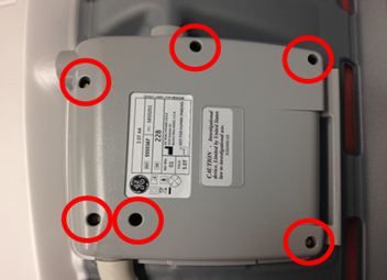
- Remove the six screws securing the cover over the system cable.
Figure 1. Cover and Screws
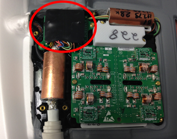
- Locate the connector of the system cable. Pull up on the connector and remove the system cable from the housing.
Figure 2. Cover and Screws
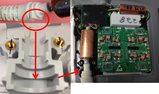
- Insert new system cable in the housing. Ensure the flat portion of the strain relief is placed in the bottom housing.
Figure 3. Strain Relief Placement
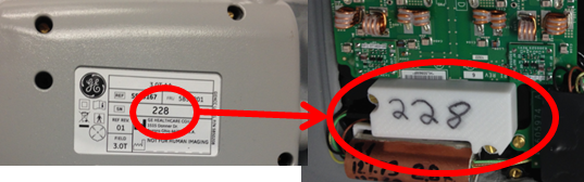
- Ensure the serial number on the cover matches the serial number inside the coil. Place cover on the coil and ensure wires leading to the system cable connector are not pinched between the housings. Secure the cover to the coil with the screws removed in step one.
Figure 4. Strain Relief Placement
Finalization
Run the MCQA Tool to verify the AA Coil operates properly.