- 00000018WHA306872GYZ
- id_200163614.0
- Dec 23, 2020 10:22:48 AM
Troubleshooting the Daily Quality Assurance (DQA) II tool
If problems are encountered while using the Daily Quality Assurance (DQA) calibration procedure, refer to the following guidelines for troubleshooting.
Procedure
- Diagnose the type of error, then use the figure and table below to determine recommended solutions.
Figure 1. Gradient direction conventions used with DQA error messages 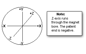
Table 1. Potential DQA tool test errors Symptom in DQA tool actions required window Recommendations One or more gradients appear not to be functioning at all. Make sure the system can properly scan images. See Reviewing DQA images and finalization for verification of proper scan for proper images. Z gradient coil appears to be driven by the wrong gradient input. or
X and Y gradient coil inputs appear to be swapped.
or
X and Y gradient polarities appear to be inverted.
or
X gradient polarity appears to be inverted.
or
Y gradient polarity appears to be inverted.
- Check coil type, phantom type, positioning, coil latches/clamps, landmarking and other checklists, if any. If an issue is found, correct it and rerun the DQA tool.
- Review the most recent DQA exam using the image browser. After reviewing the images, if corrective action is required to resolve assorted issues, see Reviewing DQA images and finalization for verification of proper body scan for proper images.
- If the error is attributed to gradient cabling, refer to Discovery MR450w Installation manual (Direction 5670002), Gradient Cable Installation.
Z gradient polarity appears to be inverted. - Check coil type, phantom type, positioning, coil latches/clamps, landmarking and other checklists, if any. If an issue is found, correct it and rerun the DQA tool.
- Review the most recent DQA exam using the image browser. Take action based on the condition that follows:
- If the latest exam has its image labeled Coronal, check to see if that image looks like the coronal sample image (regarding shape and position of phantom features) shown in Figure 3.
- If the image looks like the coronal example (even if degraded via low SNR, ghosting, distortion, and so on), suboptimal image quality may have confused the DQA tool, and the image quality issues must be resolved before running DQA calibration.
- If the acquired coronal image does not look like the coronal image example, there is probably a gradient wiring/setup problem. Proceed to the next step.
- If the latest exam has its image(s) labeled Axial, the tool has made an early detection of a Z gradient polarity problem from the set of multi-slice images. Check to see if the central bar feature (in Figure 2) moves toward the resolution comb feature as the slice location moves from inferior to superior.
- If the bar moves toward the resolution comb feature, the Z gradient is probably polarity flipped. Proceed to the next step.
- If the bar moves away from the resolution comb feature, the suboptimal image quality may have confused the DQA tool and the image quality issues must be resolved before running DQA calibration.
- If the latest exam has its image labeled Coronal, check to see if that image looks like the coronal sample image (regarding shape and position of phantom features) shown in Figure 3.
- If the error is attributed to gradient cabling, refer to Discovery MR450w Installation manual (Direction 5670002), Gradient Cable Installation.
Phantom used appears to be wrong and/or severely mispositioned. - Check coil type, phantom type, positioning, coil latches/clamps, landmarking and other checklists, if any. If an issue is found, correct it and rerun the DQA tool.
- Make sure the phantom is approximately in the center of the bore when scanning by visually checking its position.
Phantom is offset more than ±36 mm along Z. - Check coil type, phantom type, positioning, coil latches/clamps, landmarking and other checklists, if any. If an issue is found, correct it and rerun the DQA tool.
- See Laser Light Alignment. Make sure the axial alignment light is aimed straight down and lines up with the crosshairs on the DQA III phantom.
- Check that the isocenter Z value is close to the default for the magnet type. Verify that the proper magnet and magnet cover options are properly set in the MR config file.
Phantom appears to be rotated 16 degrees about the physical Z axis. - Check coil type, phantom type, positioning, coil latches/clamps, landmarking and other checklists, if any. If an issue is found, correct it and rerun the DQA tool.
- Visually inspect phantom positioning. Make sure the phantom is not rotated. A positive rotation value indicates that the phantom is rotated counterclockwise around the Z axis. The phantom needs to be rotated clockwise to correct the situation. Do not misalign the phantom when repositioning.
- If a positive value is observed for phantom rotation about the physical Z axis, rotate the phantom clockwise in the XY plane when viewing from the front of the magnet. Do not misalign the phantom when repositioning. See the Figure 4.
Phantom center appears to be offset 20 mm along physical X. - Check coil type, phantom type, positioning, coil latches/clamps, landmarking and other checklists, if any. If an issue is found, correct it and rerun the DQA tool.
- Make sure the phantom is not offset along physical X.
- If a positive value is observed for phantom position in X direction, move the phantom to the left (when viewing from the front). Do not misalign the phantom when repositioning. See the Figure 4.
Phantom center appears to be offset 20 mm along physical Y. - Check coil type, phantom type, positioning, coil latches/clamps, landmarking and other checklists, if any. If an issue is found, correct it and rerun the DQA tool.
- Make sure the phantom is not offset along physical Y.
- If a positive value is observed for phantom position in Y direction, move the phantom down (when viewing from the front). Do not misalign the phantom when repositioning. See the Figure 4.
Phantom appears to be rotated 16 degrees about the physical Y axis. - Check coil type, phantom type, positioning, coil latches/clamps, landmarking and other checklists, if any. If an issue is found, correct it and rerun the DQA tool.
- Visually inspect phantom positioning. Make sure the phantom is not rotated.
- If a positive value is observed for phantom rotation about the physical Y axis, rotate the phantom clockwise in the XZ plane when viewing the phantom from above the table. Do not misalign the phantom when repositioning.
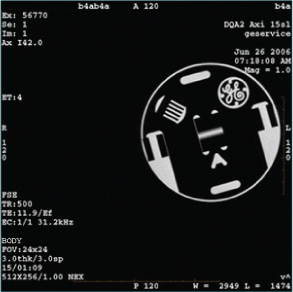
Figure 2. Example axial image at isocenter, post-calibration 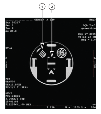
1 resolution comb 2 central bar Figure 3. Example coronal image 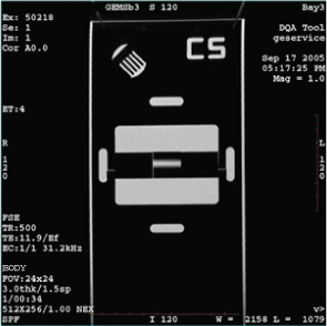
Figure 4. Example axial image with positive Z axis rotation and X axis offset