
- 00000018WIA30376950GYZ
- id_20258022.0
- Feb 22, 2021 1:44:46 AM
Emergency Off (E-Off) planned maintenance
Prerequisites
| Personnel requirements | |||
|---|---|---|---|
| Required persons | Preliminary requirements | Procedure | Finalization |
| 1 | - | - | - |
About this task
Overview
This document provides the procedure for doing a check of the EMERGENCY OFF function of the power for the entire system.
Note: To do a check of the EMERGENCY STOP function of the Power Distribution Unit (PDU) for the Gradient subsystem, and RF subsystem, see Emergency Stop (E-Stop) planned maintenance.
The PDU EMERGENCY STOP buttons are located on the Operator Workspace Keyboard and on the Magnet Enclosure front cover (two buttons, left and right). A SYSTEM OFF button is located on the System Main Disconnect Panel. The other EMERGENCY OFF buttons are located by the customer.
System shutdown
About this task
Procedure
- Click the Tools button and choose System Shutdown from the menu.Note: Shutting down the system as indicated above also shuts down the ICNs.
Figure 1. Service tools menu 
Emergency off
About this task
The AC power for the Magnet Monitor is not controlled by the Emergency Off button.
Procedure
- Turn off the breakers for the Host, ICN (Recon), and 48V Gradient Control if you are testing more E-Off buttons. Note: If you do not turn off the breakers, the Host and ICNs will restart when power is enabled again, and you will need to wait for them to boot before you can test the additional E-Off buttons.
Figure 2. Host, ICN, and 48V Gradient Control breakers 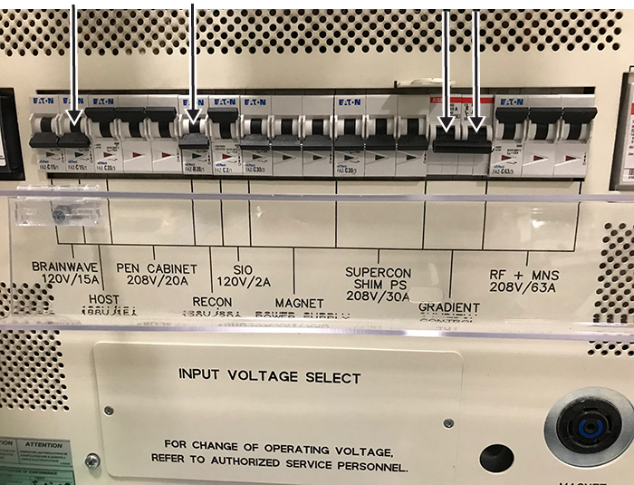
- Press one of the E-Off buttons, which will look similar to the examples in the figure below. The location of the buttons was specified by the customer, and generally they are located on the wall next to the computer equipment or next to the MR magnet room doors.
Figure 3. Example E-Off buttons 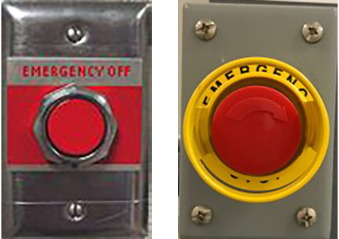
- Make sure that power was removed from the PDU by looking at the PDU phase indicator lights and examining the input voltage test points (as the lights may have burned out).
Figure 4. PDU phase indicator lights - on with power (left) and off with no power (right) 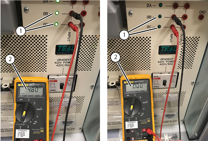
1 Phase indicator lights 2 Input voltage - Make sure that power was removed from the Heat Exchange Cabinet (HEC). The display lights on the Programmable Logic Controller (PLC) Signal Box and Variable Frequency Drive (VFD) will be off (they are green when on).
Figure 5. PLC Signal Box (left) and VFD (right) 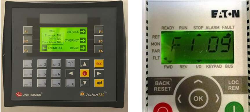
- Repeat Step 1 through Step 4 for all the other E-Off buttons, including the SYSTEM OFF button on the Main Disconnect Panel (MDP).
Figure 6. SYSTEM OFF button on the MDP 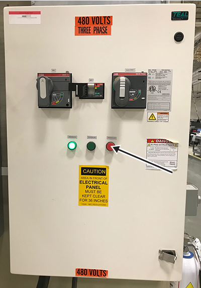
- Turn on the breakers for the Host, ICN (Recon), and 48V Gradient Control when you have tested all the E-Off buttons.
Figure 7. Host, ICN, and 48V Gradient Control breakers
Finalization
Finalization
- On the System MDP, press the SYSTEM ON button.
Figure 8. MDP controls 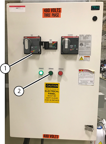
1 PDU Breaker 2 System On - Reset the PDU breaker.
- On the PDU, press the EMO RESET button.
Figure 9. PDU EMO RESET button 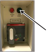
- Run the Doing a check scan procedure to make sure the system is functioning normally.