UPM Calibration and UPM Functional Check–Head Mode
Prerequisites
Table 1. Personnel requirements
Required persons
Preliminary requirements
Procedure
Finalization
1
-
30 minutes (plus 30 minutes for Agilent wattmeter power up)
10 minutes
Table 2. Tools and test equipment
Item
Quantity
Effectivity
Part number
Manufacturer
Medium Phillips screwdriver
1
-
-
-
12 inch crescent wrench
1
-
-
-
RF power measurement kit (one of the following options):
1
-
EITHER 5307511-2 or 5307511-3 (Bird wattmeter)
BOTH 5434817 (Agilent wattmeter) and 5434817-20 (dummy load)
-
Table 3. Safety
DANGER
Fatal Electric Shock Hazard!
Dangerous voltages throughout the cabinet.
Prevent fatal electrical shock by disabling the RF Amplifier before configuring the calibration tools.
Warning
Electrical/RF Burn Hazard!
RF burns can occur if transmit cables are disconnected while the system is scanning.
Prevent possible RF Burns when disconnecting transmit cables from the RF Amp by verifying that the system is not manually pre-scanning or scanning. Verify that the scan desktop icon displays the “idle” message and the RF enable switch is in the “off” position.
CAUTION
Possible equipment damage!
Coils and phantoms left in the magnet bore during these procedures can damage equipment.
Remove all phantoms and hardware (such as head coil, surface coil, etc.) from the magnet bore before initiating these procedures.
CAUTION
Possible equipment damage!
Operating the RF with an improper load can permanently damage the amplifier.
Do not operate the RF amplifier with an improper load connected to its output unless otherwise instructed.
CAUTION
Possible equipment damage!
Connecting or disconnecting the wattmeter sensor while the meter is ON can damage equipment.
Always turn the meter OFF before plugging or unplugging the sensor.
Table 4. Required conditions
Condition
Reference
Effectivity
When using the Agilent wattmeter, plug in the wattmeter and turn it on. The wattmeter must be powered for at least 30 minutes for stable and accurate readings.
-
-
About this task
Use the following procedures to calibrate the head universal power monitor (UPM) and perform the functional check for the head UPM. These procedures must be performed in sequence:
The UPM calibration adjusts digital attenuator values internal to the UPM to match the expected RF signal levels.
Calibration is performed for forward power and reflected power.
The UPM functional check runs a prescribed scan in the forward power. It compares the measured RF power from the UPM to the expected value stored in the UPM configuration file. If two values are outside 12%, the functional check fails. If the measured RF power exceeds the trip limit, the UPM stops scanning.
Dual drive RF amplifier systems operate in average power mode. Functional check tests include: 10-second average power check, RF inhibit test, and short-term average power fault host trip test.
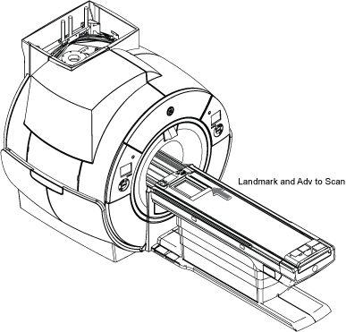
Press Landmark. Then, advance to scan. A phantom is not needed.
Note: No phantom is needed since dummy command for head connection is set in UPM Tool Head mode for SIGNA Pioneer.
Figure 3. Adv to scan
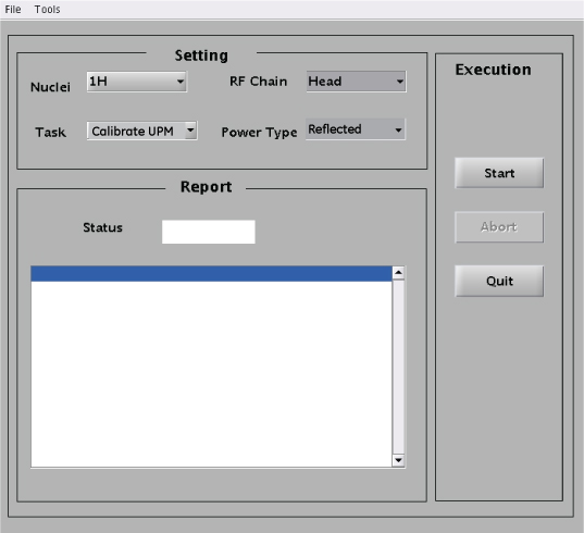
(For non-proprietary mode) On the Common Service Desktop, select Calibration > UPM Tool and select Click here to start this tool.
Set Calibrating the UPM in Head mode.
Figure 4. UPM Calibration Settings for Head Forward
For this setting:
Select:
Nuclei
1H
Task
Calibrate UPM
RF Chain
Head
Power Type
Forward
Select Start.
Select Yes when the prompt asks if the hardware setup is correct.
After approximately one minute, you are asked to confirm the peak power value output from the amplifier.
If the power read from the power meter is within specification, click Yes. Otherwise, click No and recheck the calibration of the RF amplifier.
The tool reports the steps as they progress. In about three minutes, the Status field on the UPM Tool displays PASS or FAIL.
A popup reminds you that you must run reflected power after you have run forward power.
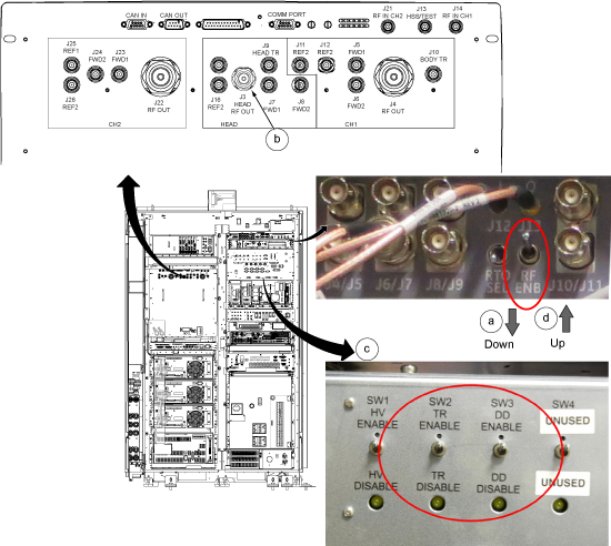
After calibrating forward power, calibrate reflected power as follows:
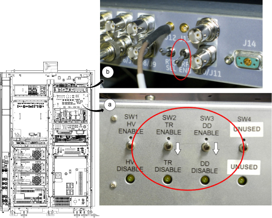
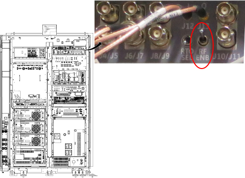
Set RF ENB to DISABLE (down).
On the front of the RF amplifier, disconnect the coupler from HEAD RF OUT/J3. Leave J3 open and unconnected.
Set RF ENB to ENABLE (up).
From the UPM Tool, make the following selections:
Figure 5. UPM Calibration Settings for Head Reflected
For this setting:
Select:
Nuclei
1H
Task
Calibrate UPM
RF Chain
Head
Power Type
Reflected
Select Start.
Select Yes when the prompt asks if the hardware is set up correctly.
Upon completion of reflected power calibration, return the cable configuration to support testing for forward power.
Set RF ENB to DISABLE (down).
On the front of the RF amplifier, connect the coupler to HEAD RF OUT/J3.
Set RF ENB to ENABLE (up).
Topic ID: id_SL12187141-1213179
UPM Functional Check for Head Channel
Procedure
After completing the UPM calibration, continue with the UPM functional check.
On the UPM Tool, make the following selections:
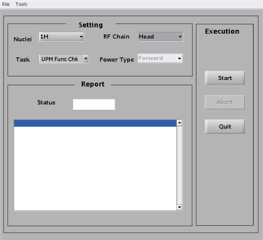
Figure 6. UPM Functional Check Settings for Head
For this setting:
Select:
Nuclei
1H
Task
UPM Func Chk
RF Chain
Head
Note:Power Type is grayed out. This is normal and is not used.
Select Start.
Select YES when the prompts ask if the hardware is set up correctly.
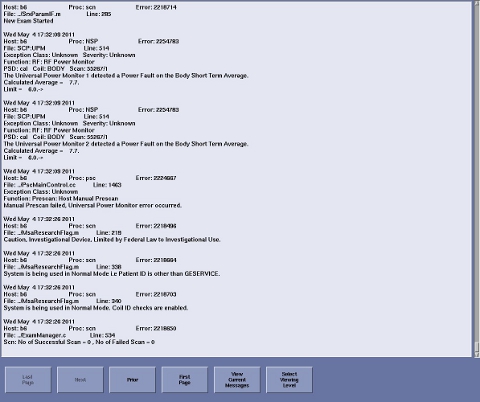
Prompts are displayed during test execution, including a pop up message about the UPM tripping and a power trip error log.
Note: The tool performs three tests (10-second average power, UPM1 RF inhibit, and UPM2 RF inhibit) before host trip. This takes 2-3 minutes before user interaction is required.
Figure 7. UPM Power Trip Error Log
When PASS appears on the UPM Tool interface, check that all the body channel is calibrated and checked.
Warning
ELECTRICAL/RF BURN HAZARD!
RF burns can occur as a result of disconnecting heliax cables while the system is scanning.
Prevent possible RF burns when disconnecting heliax cables from the RF amplifier by verifying that the system is not manually prescanning or scanning. Verify that the scan desktop icon displays the “idle” message and the RF enable switch is in the "off" position.
Notice
Possible equipment damage. Do not connect/disconnect the wattmeter sensor while the wattmeter is ON. Always turn the wattmeter OFF before plugging/unplugging sensor.
Restore RF cables per following steps.
Set the RF ENB switch to DISABLE (down).
Disconnect the RF coupler from J3 and reconnect the head and transmit cables.
Re-enable the TR and DD fault switches on the front of the driver module.