
- SIGNA™ Hero 3.0T Service Methods
- 5852800-8EN Revision 1.0
- 00000018WIA30121E20GYZ
- id_131059723.0
- Aug 29, 2019 1:39:51 AM
Agilent Wattmeter and Power Adjustment Kit for RF Head Calibration
Prerequisites
| Required persons | Preliminary requirements | Procedure | Finalization |
|---|---|---|---|
| 1 | Not Applicable | Part of parent procedure minutes | Not Applicable |
Procedure
- Setup the hardware per following steps.
- Disconnect the head output cable from J3 on the front of the RF amplifier.
- Connect the input of the coupler to J3 on the RF amplifier.
Figure 1. Setup hardware 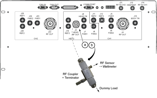
- Connect the remaining Agilent power components as shown below.
Figure 2. Agilent Wattmeter Setup for RF Power Output for Head 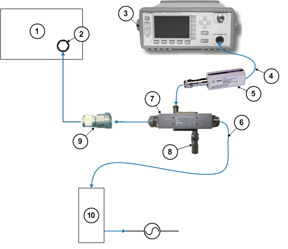
1 RF amplifier (front) 6 RF cable to dummy load 2 RF output port 7 RF coupler 3 Wattmeter 8 Agilent 50 ohm terminator connected to the Reflected port on the coupler 4 Agilent sensor probe cable 9 RF adapter 5 RF sensor connected to the Incident port on the coupler 10 Dummy load with internal fans
Finalization
No finalization steps.