• SIGNA™ Hero 3.0T Service Methods
  • 5852800-8EN Revision 1.0
  • Object ID: 00000018WIA30D11E20GYZ
  • Topic ID: id_13106516 Version: 3.0
  • Date: Aug 29, 2019 1:39:50 AM

Bird 5000-EX setup for RF Head Calibration

Prerequisites

Table 1. Personnel requirements
Required personsPreliminary requirementsProcedureFinalization
1Not ApplicablePart of parent procedure minutesNot Applicable
Topic ID: id_SL13643180-1274800

Setting up RF Coupler for Head Calibration

Procedure

  1. Insert the 5 kW element into the Forward sensor port, (blue 4300A374-6). Make sure the arrow on the element points in the direction of the arrow (from Input to Output) on the sensor. Lock the element in place using the locking tab on the sensor.
    Figure 1. RF Coupler Setup for Head Mode
  2. Insert the 50 kW element into the Reflected sensor port (blue 4300A374-3). Make sure the arrows on the elements point in opposite directions. Lock the element in place using the locking tab on the sensor.

    The Reflected port is not used during this procedure. Placing the 50 kW element into the Reflected port is a safety measure.

  3. Use the DVM to measure the resistance of input to the dummy load. Confirm that the resistance measures 50 ohms +/- 5 ohms.
    Note:

    If the dummy load is out of specification, return the RF kit for repair. Do NOT proceed with the RF amplifier output calibration.

Topic ID: id_SL13643181-1274800

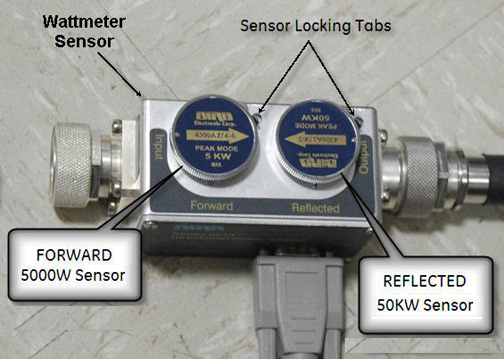
Wattmeter and Dummy Load Setup for Head Mode

Procedure

  1. Verify that the scanner is idle. Confirm that the RF ENB switch on the DTX1 exciter is in the Disable (down) position.
  2. Setup the hardware per following steps.
    1. Disconnect the head output cable from J3 on the front of the RF amplifier.
    2. Connect the input of the coupler to J3 on the RF amplifier.
    Figure 2. Connection of RF Coupler to Head Output
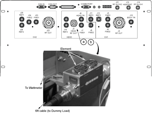
  3. Connect the RF coupler output to the dummy load.
    Figure 3. Complete Head Output Test Setup
  4. Plug in the wattmeter to use wall power (batteries are often not charged). Connect one end of the wattmeter cable to the wattmeter sensor output connector (RS232 is unused). Connect the other end to the coupler.
  5. Plug the fan for the dummy load into a service outlet in the ISC. Never use this dummy load without its fan running.
  6. Set the RF ENB switch to ENABLE (up).
Topic ID: id_SL13643182-1274800

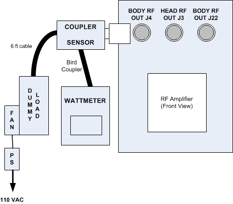
Setting up Bird 5000-EX Wattmeter to Measure Forward Head Maximum Power

About this task

This procedure is for the Bird 5000-EX only.

Procedure

  1. Press the ON button on the wattmeter. (If the coupler and sensor are not correctly attached to the amplifier, you will see a No Sensor indication).
  2. Select the arrow button under Scale.
  3. Type 5000 to set the range and then press Enter.
  4. To validate the setting, select the arrow button under Scale.
  5. To exit, press Enter.
  6. Select the arrow button under Fwd Units. Make sure the scale reads W (or kW on some wattmeters). If the scale reads dBm, select the arrow button under Fwd Units again to toggle the scale to read W (or kW) on the TOP, forward power scale. Ignore the BOTTOM, reflected power scale value. It is not used during maximum power calibration.
  7. Select the Shift button.
  8. Select the arrow button under Setup.

    This action displays the sensor type configured in the wattmeter. This procedure uses sensor type 43, which is optimized for peak power measurement.

  9. Verify that the wattmeter display reads 43. If not, type 43 and then press Enter.
    Figure 4. Wattmeter Display Set to Read Sensor Type
  10. Press Enter.
  11. Select the arrow button under Type, and change the unit of measurement to Peak.
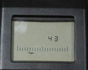
  12. Some kits require an offset to ensure accurate measurement. Locate the Element Offset Factors card in the kit.

    Find the offset for “3T DVMR Head Output,” “4500 W”.

    Figure 5. Example Element Offset Factors Card
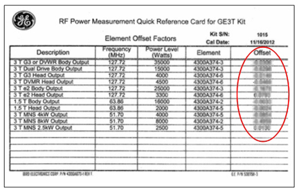
  13. Press the Offset button on the wattmeter. Enter the numeric value from the offset card, and press Enter.
    Note:

    If entering a negative value, first enter the numerical value, then the minus symbol (–).

    Figure 6. Wattmeter Set to Display Peak Power and Watts
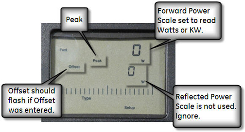
  14. The meter is now configured to read RF peak power, in watts, for the head maximum output calibration.
Topic ID: id_14935585

What to do next

Finalization

No finalization steps.