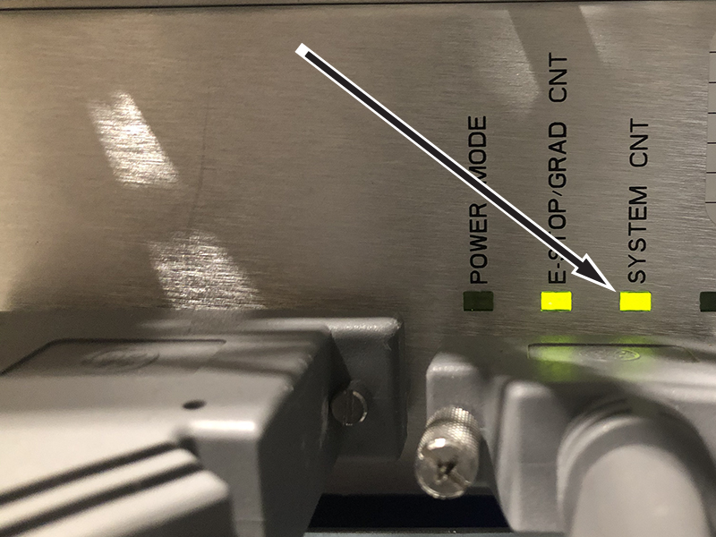
If the System CNT LED is illuminated, the CabMon3 ISR is ready to supply 120 VAC. Continue on to Step 3.
If the System CNT LED is not illuminated, continue on to Step 2.
Make sure the CabMon3 ISR is receiving 120 VAC power on connector J1.
If CabMon3 ISR has 120 VAC at connector J1, replace the CabMon3 ISR.
If CabMon3 ISR does not have 120 VAC at connector J1, make sure it is wired to the PDU correctly and repeat Step 1.
Make sure 120VAC is present at the PDU connector J1 using a DMM set to AC voltage.
Put the positive probe in connector J1 pin 2 (System Contactor Coil).
Put the the negative probe in connector J1 pin 1 (Neutral).
If 120 VAC is measured, the problem is within the PDU. See Troubleshooting the PDU.
If 120 VAC is not measured, continue on to Step 4.
Power down the CabMon3 ISR and remove connector J2. Use a DMM to check resistance in the contactor power cable (5749299-2) to verify continuity.
If the contactor power cable is verified to be good, replace the Cabinet Monitor 3 ISR (5789922).
If the contactor power cable is bad, replace the cable and repeat Step 1 through Step 4.
Finalization
After the issue is resolved and all assemblies are properly connected, test the E-Stop circuit by pressing one of the E-Stop buttons, and then recover by pressing the EMO Reset button. This verifies the E-Stop circuit is functioning properly.