- SIGNA™ Hero 3.0T Service Methods
- 5852800-8EN Revision 1.0
- 00000018WIA3077A230GYZ
- id_156675141.7
- Apr 23, 2020 6:48:19 PM
Magnet Enclosure Alignment Troubleshooting
| Notice | |
|---|---|
This document describes various error conditions for the Magnet Enclosure Alignment and possible solutions.
| Notice | |
|---|---|
| Notice | |
|---|---|
Go to the following sections to resolve issues:
- Left Side: Large gap between side bottom cover and front/rear cover
- Left Side: Misalignment of side beam
- Left Side: Access Cover Interferes with side electronics
- Left Side: Distorted Arc Cover
- Left Side: Not able to fix side access cover
- Right Side: Large gap between side bottom cover and front/rear cover
- Right Side: Side upper covers are pulled by side beam at the center of magnet
- Right Side: Misalignment of side beam to lower direction
- Right Side: Misalignment of side beam to upper direction
- Bottom latch is hard to engage even though there is no gap between side bottom cover and front cover
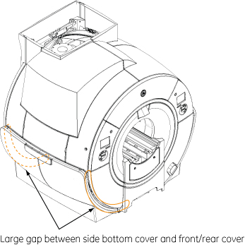
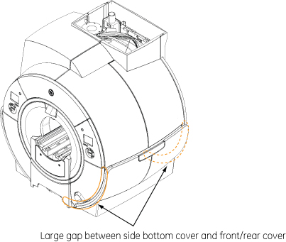
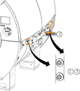
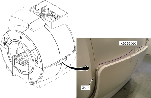
Left Side: Large gap between side bottom cover and front/rear cover
Observation
Large gap between left side bottom cover and front/rear cover.
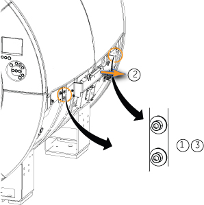
Alignment
-
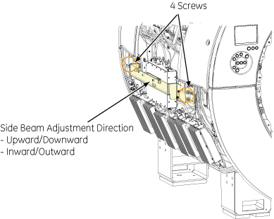
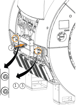
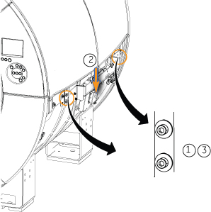
Mark the screws and bracket location. Then, loosen four screws.
-
Move the side beam inward to adjust the position.
-
Tighten the four screws. Then, check the side bottom cover gap after installing it.
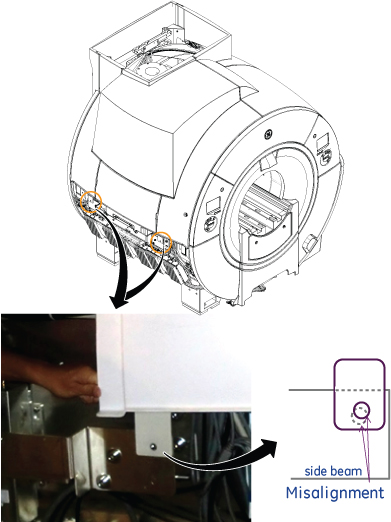
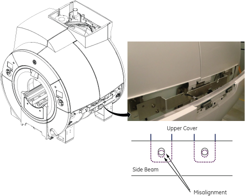
Left Side: Misalignment of side beam
Observation
Misalignment of left side beam
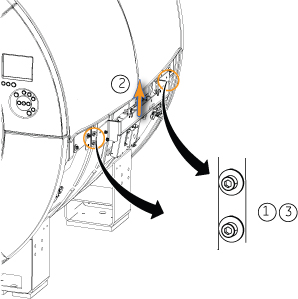
Alignment
-
Mark the screws and bracket location. Then, loosen four screws.
-
Move the side beam upward to adjust the misalignment.
-
Tighten the four screws and check the alignment.

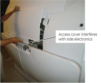
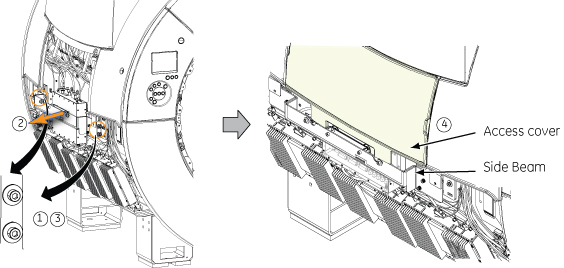
Left Side: Access Cover Interferes with side electronics
Observation
Access Cover Interferes with side electronics
Alignment
-
Mark the screws and bracket location. Then, loosen four screws.
-
Move the side beam outward to adjust the position.
-
Tighten the four screws.
-
Check that the access cover can be inserted between side beam and side electronics without interference.
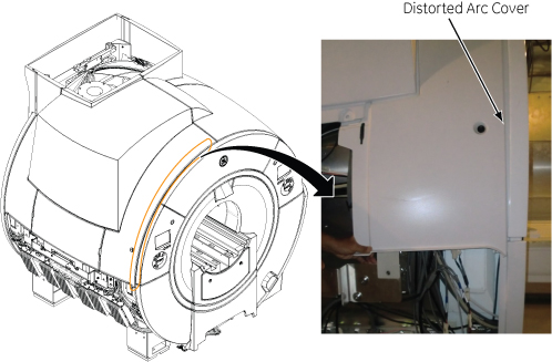
Left Side: Distorted Arc Cover
Observation
Distorted Arc Cover
Alignment
-
Mark the screws and bracket location. Then, loosen four screws.
-
Move the side beam upward.
-
Tighten the four screws and check the alignment.
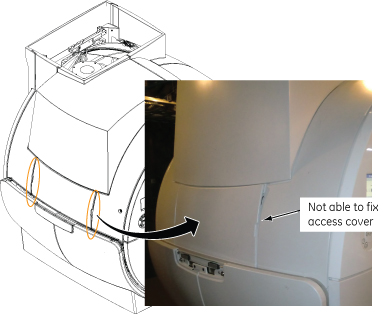
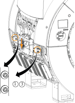
Left Side: Not able to fix side access cover
Observation
Not able to fix side access cover.
Alignment
-
Mark the screws and bracket location. Then, loosen four screws.
-
Move the side beam downward.
-
Tighten the four screws and check the alignment.
Right Side: Large gap between side bottom cover and front/rear cover
Observation
Large gap between right side bottom cover and front/rear cover
Alignment
-
Mark the screws and bracket location. Then, loosen four screws.
-
Move the side beam inward to adjust the position.
-
Tighten the four screws. Then, check the side bottom cover gap after installing it.
Right Side: Side upper covers are pulled by side beam at the center of magnet
Observation
Right Side upper covers are pulled by side beam at the center of magnet
Alignment
-
Mark the screws and bracket location. Then, loosen four screws.
-
Move the side beam outward to adjust the position.
-
Tighten the four screws. Check that upper covers are aligned properly.
Right Side: Misalignment of side beam to lower direction
Observation
Misalignment of right side beam to lower direction

Alignment
-
Mark the screws and bracket location. Then, loosen four screws.
-
Move the side beam upward to adjust the misalignment.
-
Tighten the four screws and check the alignment.
Right Side: Misalignment of side beam to upper direction
Observation
Misalignment of right side beam to upper direction
Alignment
-
Mark the screws and bracket location. Then, loosen four screws.
-
Move the side beam downward to adjust the misalignment.
-
Tighten the four screws and check the alignment.
Bottom latch is hard to engage even though there is no gap between side bottom cover and front cover
Observation
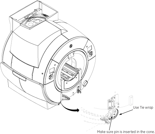
Bottom latch is hard to engage even though there is no gap between side bottom cover and front cover
Alignment
Use Tie wrap fix the bottom cover to the latch. Make sure the pin is inserted in the cone.
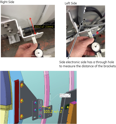
Reference: Position of side bracket
Default position of side bracket at manufacturing is as follows.
-
Measurement position: Upper screw hole to magnet (horizontal) 4 brackets.
-
Nominal distance: 103.2 mm
-
Tolerance: +/- 2 mm
| Notice | |
|---|---|