
- SIGNA™ Hero 3.0T Service Methods
- 5852800-8EN Revision 1.0
- 00000018WIA3024C230GYZ
- id_156671031.3
- Jan 14, 2020 9:48:43 PM
ICC F-50 Emergency backup water Connection
Prerequisites
| Required persons | Preliminary requirements | Procedure | Finalization |
|---|---|---|---|
| 1 | Not Applicable | 30 minutes | Not Applicable |
| Item | Quantity | Effectivity | Part number | Manufacturer |
|---|---|---|---|---|
| Standard Tool | 1 | - | - | - |
| 1/2” Hoses for tap water supply and draining (Customer supplied) | 2 | - | - | - |
| Hose bands for 1/2” Hoses | 2 | - | - | - |
| nipple and nut pair for hose (shipped with ICC) | 2 | - | - | - |
| Item | Quantity | Effectivity | Part number | Manufacturer |
|---|---|---|---|---|
| Towels | NA | - | - | - |
| ||||
About this task
This procedure is required if Facility water chiller is stopped by any reason and need to run F-50 using emergency backup water.
Procedure
- Confirm that F50 Power is OFF. If not perform the following steps.
- Turn off the “Drive Switch”.
- Turn off the “Main Power Switch”.
Figure 1. F50 Power OFF 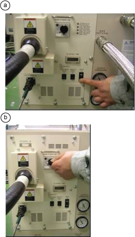
- Open cap of tap water supply and drain ports per the following steps.
- Confirm that valves for Tap water supply drain ports are closed.
- Open cap of tap water supply and drain ports.
Figure 2. Open cap of tap water supply and drain ports 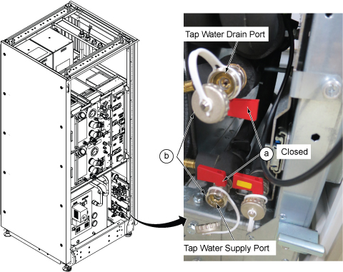
- Connect nipples to tap water supply and drain ports per the following steps.
- Find nipples and nuts which was shipped with ICC.
- Make two pares of nipple and nut.
- Fix the nipples to the two ports.
Figure 3. Fix the nipples to the two ports 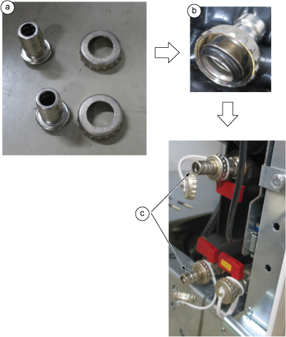
- Connect 1/2” Hoses to the nipples and fix them with hose bands.
Figure 4. Hose connection 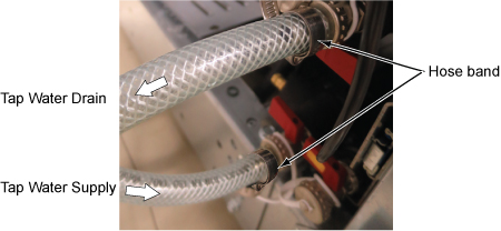
- Remove the lower small door, close ICC Front Cover, and confirm the hose routing.
Figure 5. Hose routing 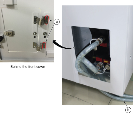
- Set the valves for F-50 as follows.
- Close the valves for in and out lines of the cryogen compressor.
- Open Emergency tap water supply and drain valves.
Figure 6. Valve operation 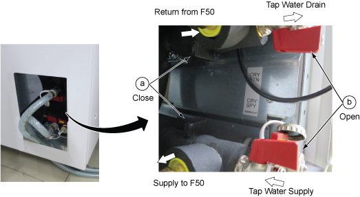
Finalization
No finalization steps.