- SIGNA™ Hero 3.0T Service Methods
- 5852800-8EN Revision 1.0
- 00000018WIA30234660GYZ
- id_20320511.29
- Oct 27, 2021 1:23:57 PM
IRD troubleshooting
Diagnose and fix issues with the 12.1 inch IRD screen.
| Notice | |
|---|---|
| Notice | |
|---|---|
FRU components for this troubleshooting
The following are main components around IRD
| Description | FRU Number |
|---|---|
| MR Compatible 12.1 inch In Room Display | 8771126-61 |
Run P5006 Cable Harness, GOC to IRD Fiber Optic
| 5875244
|
| IRD DCPS | 6859114-2 |
| Dell T5820 MR Global Host W-2123 64GB Nvidia SSD | 8780011-02 |
| NEC P242W 24in LCD Monitor | 5430786-2 |
| Main Monitor Mini DP to DP Cable | 5795593 |
| Mini DP to DP Dongle for port 1 | 5851077-2 |
| Mini DP to DP Dongle for port 2 | 5851077-3 |
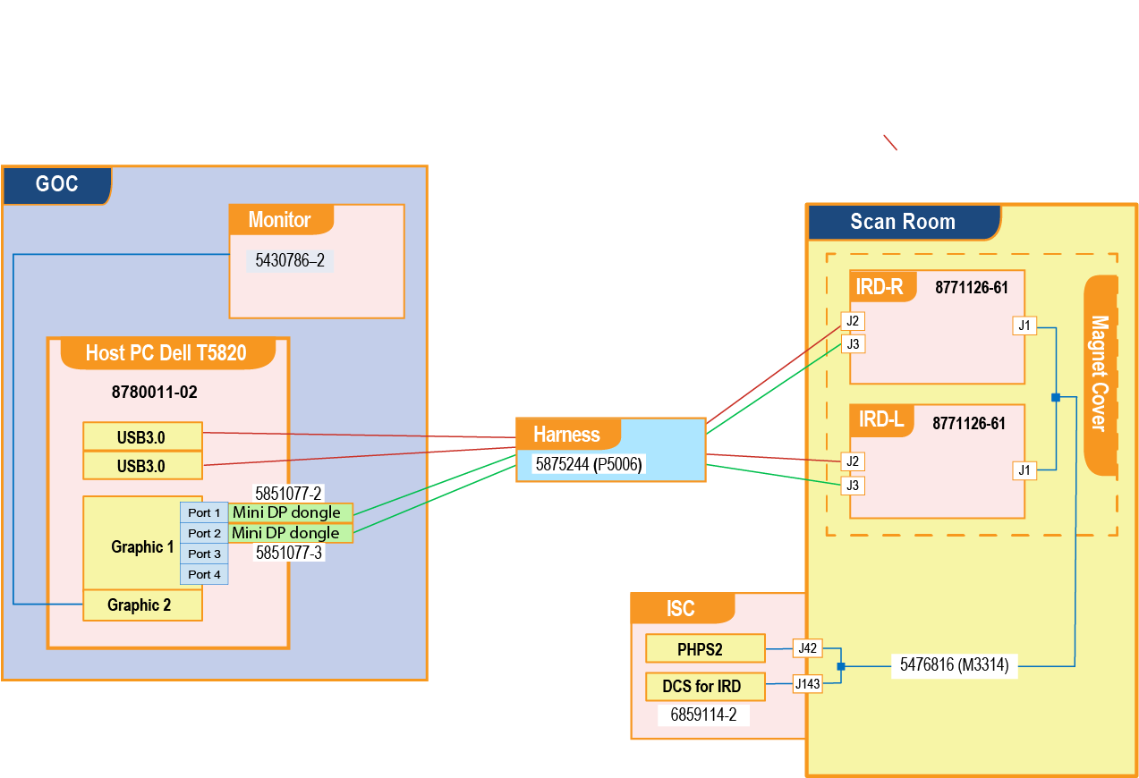
Block Diagram
The following block diagram is used in the theory of troubleshooting throughout this document.
Troubleshooting steps
Make sure the IRDs have power
If there is no power, confirm M3314 connections to and .
For systems with Remote (off the wall) siting configuration:
- Confirm E3314 connections to and .
- Confirm E3302 connections to and .
Replace cables if necessary.
Make sure the fiber optic cables are connected
Make sure the USB fiber optic cables P5006 are properly connected to the correct USB 3.1 ports on the GOC. Refer to Figure 1 for more information.
Make sure the connections are clean
- Disconnect the PHPS power, DP, and USB 3.0 cables from the IRD(s).
- Check the connectors for debris or damage and clean or replace if required.
- Reconnect the cables.
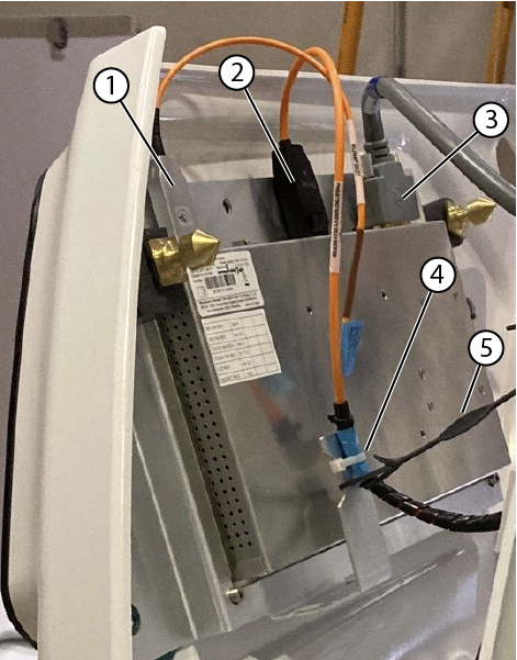
| 1 | USB cable |
| 2 | DP cable |
| 3 | Power cable |
| 4 | Tie wraps |
| 5 | Lanyard |
Make sure the IRDs are connected to the host PC
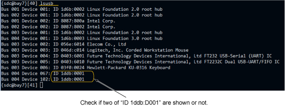
Make sure that two displays and two mouse devices are detected by the Host PC.
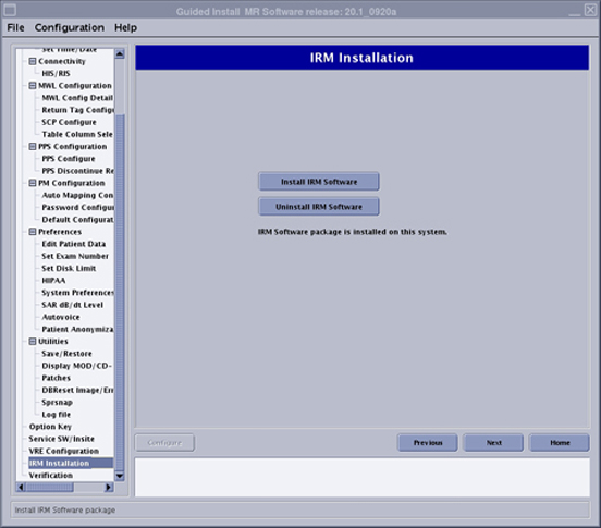
If necessary, re-install IRM software to resolve problem. See Figure 7.
Resolve issue if one of the IRDs does not work
- Re-install the IRM software and check if the issue is resolved. See Figure 7.
- Swap the malfunctioning IRD and working IRD.
Follow these procedures to remove the control panel covers:
- Removing the magnet left- and right-hand lower access panels
- Removing the dockable table interface cover
- Removing the magnet left and right control panel covers
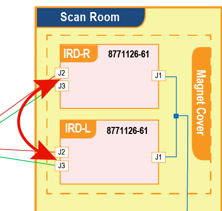
Figure 3. Swap IRD Swap the right and left IRD.
If the same IRD is malfunctioning, then replace the IRD. Follow the instructions in Replacing the In-Room Display (IRD).
- If the problem moves to the other IRD, there may be a problem with the cables or the GOC port.
- Go to the GOC and confirm the cables are properly seated and connected as described in the block diagram. If no issues are found go to the next step.
- For touch related issues, swap the USB cable connections on the GOC ports.
- If the problem stays on the same IRD, replace the USB cable.
- If the problem moves to the other side IRD, there could be a problem with the GOC port.
- Move the USB connections back to the default ports. Reboot the Host PC to see if that resolves the issue.
- If problem is not resolved, connect the USB cable to an open USB port. Reboot the Host PC to see if that resolves the issue.
- If no open USB ports are available or if the problem is not resolved by rebooting the Host PC, replace the Host PC.
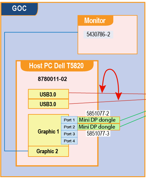
Figure 4. Swap USB Cable on Equipment Room side to troubleshoot touch screen Swap the USB cables at the USB ports of the host PC. A hot swap is permitted.
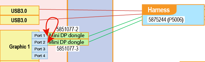
- For display related issues, swap the mini DP cable connections on the GOC ports including the dongle. Important: Handle the cables carefully, the fiber optic cables are easily damaged and have a minimum bend radius of 50 mm.
- If the problem stays on the same IRD, swap the Mini DP to DP Dongle
for port 1 (5851077-2 ) with the Mini DP to DP Dongle
for port 2 (5851077-3) to check if the issue is with the dongle.
If the problem stays on the same IRD, replace the cable. Otherwise replace the Mini DP to DP Dongle.
- If the problem moves to the other side IRD, there could be a problem with the GOC port.
- Move the DP connections back to the default ports. Re-install the IRM software to see if that resolves the issue. See Figure 7.
- If the problem is not resolved, connect the DP cable from the malfunctioning mini DP port to one of the open mini DP ports. Re-install the IRM software to see if that resolves the issue.
- If the problem is not resolved by connecting to an open mini DP port or by re-installing the IRM software, replace the Host PC.
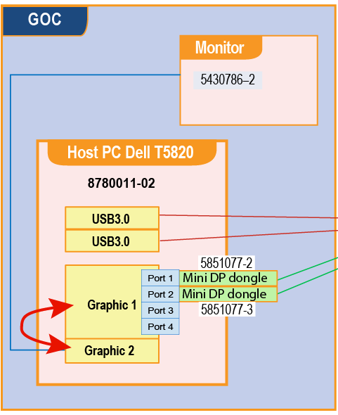
Figure 5. Swap DP Cable on Equipment Room side to troubleshoot display Swap the DP cables. A hot swap is permitted if you are reusing earlier ports.
 Note: If cables are moved to new ports, you must reinstall the IRM software. See Figure 7.
- If the problem stays on the same IRD, swap the Mini DP to DP Dongle
for port 1 (5851077-2 ) with the Mini DP to DP Dongle
for port 2 (5851077-3) to check if the issue is with the dongle.
Resolve “No signal” message
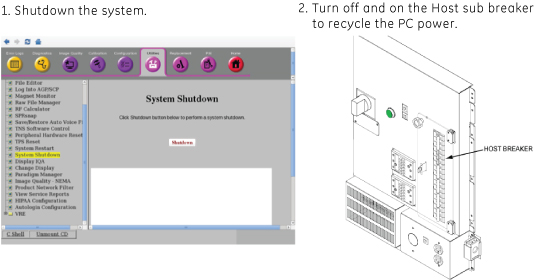
If both IRDs display No signal, determine if the system has been idle for more than 2 hours. The IRDs can lock due to noise exposure on the video line. When this happens, do the following to power cycle the IRD monitor.
- Press the E-stop button on the SCIM.
- Press the green EMO RESET on the PDU.
Finalization
- If you removed covers, reinstall them:
- Make sure all system interconnects are returned to normal configurations.
- Run the Check scan.
Reference : Backmatter of IRD Troubleshooting
Swap the video cable between the graphic cards. A hot swap is permitted.
Open Guided Install, select IRM Installation, and then click Install IRM Software to install IRM software.
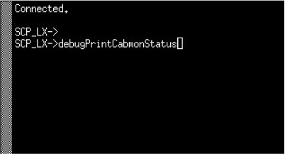
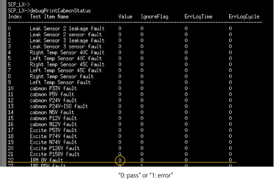
Enter “debugPrintCabmon” in ICE Term
Refer to Running ice_term to open ice_term window.
Enter debugPrintCabmonStatus.
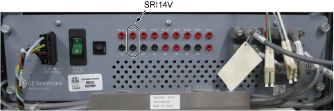
Check SRI14V on PHPS Front Panel is in spec. (Spec: 13.3~14.7VDC)