USE PROPER LOTO PROCEDURES BEFORE REPLACING THE COMPONENTS.
See the MR Service Safety Manual, PN 5452735.
Warning
POSSIBLE PERSONAL INJURY!
THIS PROCEDURE REQUIRES Movement OF highly FERROUS MATERIAL
IN CLOSE PROXIMITY TO THE MAGNET. ANY FIELD STRENGTH > 200 GAUSS WILL
FORCIBLY ATTRACT THE BLOWER BOX.
STAY OUTSIDE THE 200 GAUSS LINE WHEN MOVING THE BLOWER
BOX. KEEP AS FAR FROM MAGNET AS POSSIBLE AND see the MR Service Safety
Manual, PN 5452735. SEE Figure 5 FOR PROPER METHOD for two people TO REMOVE and mount BLOWER BOX
FROM MAGNET ROOM. MULTIPLE Field engineers are required at all times.
Warning
Personal injury and equipment damage
If the magnet is energized, tools and loose materials that contain ferrous material will be strongly attracted to the magnet and may become dangerous projectiles.
When servicing any magnetic equipment, it is critically important that the service engineer consciously plan the path to be taken when moving highly ferrous devices within the magnet environment. The path should be as far from the magnet as practical and avoid high flux-density fields.
Movement of ferrous material in the magnet room must follow the GE service procedure for that device.
When exiting, move away from the magnet in the most direct manner possible. Except when moving ferrous material to and from its native location on or near the magnet, the static magnetic field in any portion of the service path shall not exceed 200 Gauss.
Two (2) MR safety trained personnel must be present at all times when servicing highly ferrous devices in the areas of magnetic fields.
When planning a service path, it is critical that the path be clear and sufficiently wide. Make sure that there are no trip hazards, obstacles, clutter, slippery surfaces, or other items even partially restricting the path. If there are portable obstacles in a path, remove them from the area and replace them after the service action is completed. It is required to walk the path prior to beginning service to ensure that there is sufficient space through which to pass for yourself and the object being serviced.
Notice
MATERIAL DAMAGE!
ANY FIELD STRENGTH > 200 GAUSS WILL FORCIBLY ATTRACT THE BLOWER
BOX.
STAY OUTSIDE THE 200 GAUSS LINE WHEN MOVING THE BLOWER BOX.
KEEP AS FAR FROM MAGNET AS POSSIBLE AND SEE THE MR SERVICE SAFETY
MANUAL, PN 5452735.
Table 6. Required conditions
Condition
Reference
Effectivity
All persons performing this procedure must complete GE-certified
MR safety training.
-
-
Topic ID: id_SL1985853-1061492
Power Down and LOTO
Procedure
DANGER
electrocution hazard!
Extremely high voltage present in ac power filter panel.
the blower box power supply panel yields 208 volts. Follow
proper LOTO procedures for the PEn panel. See the MR Service Safety
Manual, PN 5452735.
Perform LOTO on the PEN cabinet. See the MR Service
Safety Manual, PN 5452735.
Topic ID: id_SL1985855-1061492
Removing Blower Box
Procedure
Allow five minutes for the filters to discharge. After five
minutes, check capacitors for discharge with grounded cable on DVM.
Remove any cable ties on the blower box power cable.
In the magnet room, remove the two top screws and two bottom
screws from the blower box power supply cover on the lower right corner
of the PEN panel.
Figure 1. Blower Box Power Supply Cover
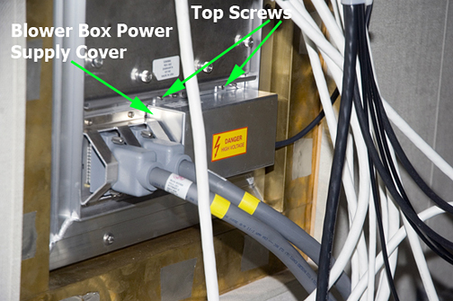
Be sure the power cables are properly marked or labeled for
later reconnection. Disconnect the power cable connectors from the
AC power filters. See Table 7for a list of cables and connections.
Note:
The single blower box has five power cables. The dual
blower box has seven power cables.
Figure 2. AC Power Filters
Follow the cable path and confirm that the cable is free of
the penetration wall and will not tangle when the blower box is removed.
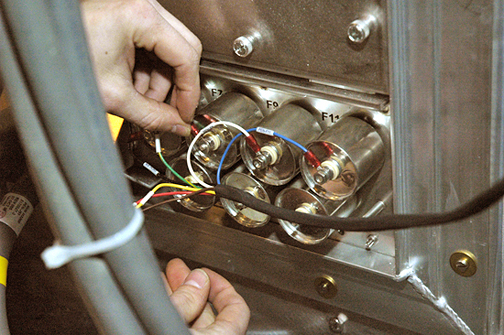
Remove both air hoses at the top of the blower box.
Systems with the RRx receive chain use the dual blower box, which uses two hoses to provide air for both patient comfort and the RF hub.
Note:
Mark or label the two air hoses at the top of the blower
box to note their mounting location.
Figure 3. Air Hose Clamps
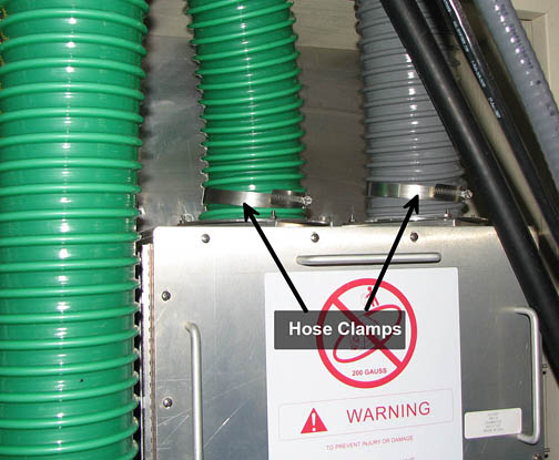
Note:
Some sites have a closet service hatch installed in the
scan room wall. Use the closet service hatch to safely remove the
blower box from the scan room.
Loosen, but do not remove, the four screws securing the blower
box to the PEN panel.
Note:
If the slot on the mounting flange does not provide enough
clearance for placing over the existing flange studs, remove the mounting
screws, position the blower box on the SPW, and attach with the removed
screws.
At least two people are required for this procedure.
Figure 4. Side View of Blower Box
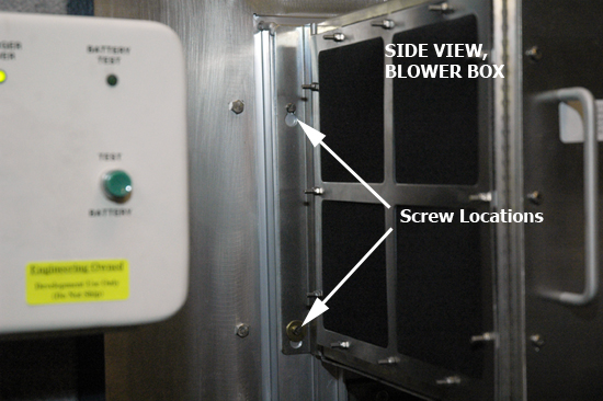
DANGER
BODILY INJURY!
ANY FIELD STRENGTH > 200 GAUSS WILL FORCIBLY ATTRACT THE
Blower Box.
STAY OUTSIDE THE 200 GAUSS LINE WHEN MOVING THE BLOWER
ASSEMBLY. KEEP AS FAR FROM MAGNET AS POSSIBLE AND SEE THE MR SERVICE
SAFETY MANUAL, PN 5452735.
Warning
POSSIBLE PERSONAL INJURY!
ANY FIELD STRENGTH > 200 GAUSS WILL FORCIBLY ATTRACT THE
Blower Box.
DO NOT PLACE ANY PART OF THE HUMAN BODY IN THE PATH BETWEEN
THE Blower Box AND THE MAGNET.
Notice
To ensure a safe distance, make sure that the clear path through which you will be moving the blower box is completely outside the 200 Gauss line. The distance to the 200 Gauss line is in the Pre-Installation Manual (PIM). Gauss plots are in the section titled “MR Suite Minimum Room Size Requirements”.
THE 200 GAUSS LINE MAY NOT BE WITHIN THE MINIMUM SERVICE AREA. IF THERE IS NOT ENOUGH ROOM TO MOVE THE BLOWER BOX OUTSIDE OF THE 200 GAUSS LINE, THE MAGNET MUST BE RAMPED DOWN PRIOR TO CONTINUING.
With two people holding the blower box, exit the
magnet room by walking as close to the wall on the coldhead side of
the magnet as possible. See Figure 5.
Topic ID: id_SL2027687-1061492
Installing New Blower Box
About this task
The following steps explain how to install the scan room blower box.
Procedure
With two people holding the blower box, stay as far away from
the magnet as possible as you bring the blower box into the magnet
room and position it on the PEN panel. See Figure 5. Refer to note inStep 8 above to determine safe distance.
Note:
Some sites have a closet service hatch installed in the
scan room wall. Use the closet service hatch to safely insert the
blower box into the scan room.
With two people, lift and slide the blower box mounting holes
over loosened screws on the PEN panel
Note:
If you had to remove one or more of the screws during
the removal process, one person must hold the blower box in place
while the second person installs the screws.
With one person holding the box in place, tighten the four screws
to secure the blower box to the PEN panel frame.
Figure 5. Mounting New Blower Box
Warning
ARC Flash/Electrocution Hazard
High voltages may exist in the MDP.
Make sure you wear appropriate personal protective equipment (PPE). For example, Americas Service would use appropriate PPE for Category II Arc Flash PPE.
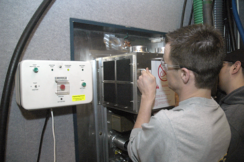
Attach the blower box power cable to the power supply panel filters, matching the labels on each connector to its corresponding filter.
Important: Arc flash may occur if exposed terminals contact AC power filter connections.
Note:
There should be a washer above and below each ring terminal on the filter stud.
Figure 6. AC Power Filter Cable Connections
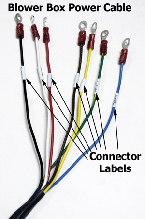
Table 7. Cables and Connections
Power cable color
PEN panel AC power connection
Blower type (single, dual, or both)
Blue
PEN-F11
Both
Yellow
PEN-F10
Both
Red
PEN-F9
Both
White
PEN-F8
Both
Green and yellow
PEN-F7
Both
Brown
PEN-F6
Dual blower only
Black
PEN-F5
Dual blower only
Replace the power supply cover. Ensure the cable is routed through
the cable access hole, and is not pinched under the cover. The warning
label should be upright.
Note:
The length of the power cable from the bottom of the blower
box to the power supply filter panel provides enough slack to run
the cable along the right side of the PEN panel using cable ties to
hold the cable in place.
Replace the air hose connections, noting the correct location.
Secure the air hose by tightening the worm gear hose clamps. Pull
on each hose to confirm the hose is securely fastened to the blower
box.
Topic ID: id_15255635
Finalization
Procedure
Remove LOTO from the PEN cabinet. See the MR Service
Safety Manual, PN 5452735.
Ensure air is flowing to the patient bore.
(For systems equipped with the legacy RF hub) : Ensure air is flowing to the RF hub.