Failed Gradient Body Coil Removal
Prerequisites
After the Gradient Body Coil is completely disconnected, follow either of two procedures:
-
If the RF Body Coil is operational, it must be removed for later installation in the replacement gradient coil. In this case, proceed to Step 1
OR
-
If the RF Body Coil is to be replaced along with the Gradient Coil, proceed to Replacement Coil Installation.
note:For more information, refer to Gradient Coil Replacement Introduction.
1 Failed Gradient Body Coil Removal
Procedure
- notice
- Ensure that RF power and DD Board Bias cables are already disconnected and ends taped to the inside of the coil.
- notice
- Remove the RF Body Coil as described below:
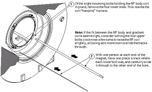
- Refer to the illustration below for proper placement of the
RF Body Coil installation nylon tracks.
Figure 1. Positioning Nylon Tracks
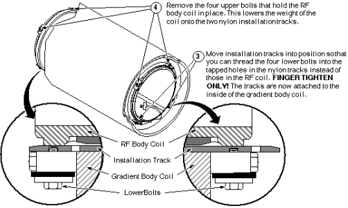
- Attach the RF Body Coil installation tracks as described below.
Figure 2. Attaching RF Body Coil Installation Tracks
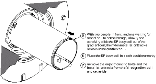
- Remove the RF Body Coil from the Gradient Coil as described
in the following illustration.
Figure 3. Removing RF Body Coil from Gradient Coil
 note:
note:If the fit between the RF and Gradient Body Coils seems tight, consider turning the four upper bolts clockwise a few turns to raise the RF Coil slightly, allowing a more room to slide the tracks through.
Proceed to the next section.
- Refer to the illustration below for proper placement of the
RF Body Coil installation nylon tracks.
 |
|
2 Using Coil Cradle and Cart
Procedure
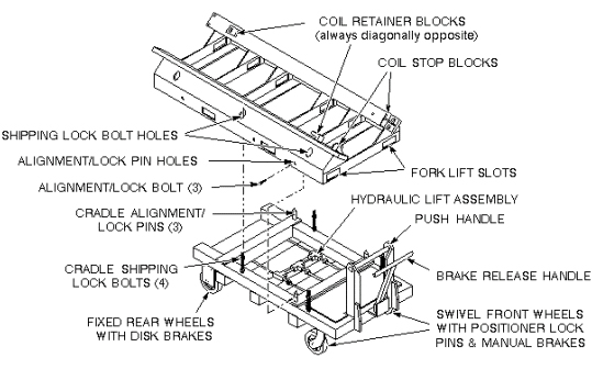
- The Epoxy-filled Gradient Coil cradle and cart are used to install
and remove the Epoxy-filled Gradient Coil (with or without the RF
Body Coil) at the magnet. Study the components identified below, as
well as referring to Service Note 60880 82239.pdf for more information
on using the Gradient Coil Cart.
Figure 4. Components of Gradient Body Coil Cradle and Cart
 warning
- caution
- caution
- Moving the almost 3.300 pounds of the combined coil, cradle,
and cart requires a minimum of four people; therefore, follow the
steps below to prevent damage to the equipment, and for the safety
of those using that equipment.
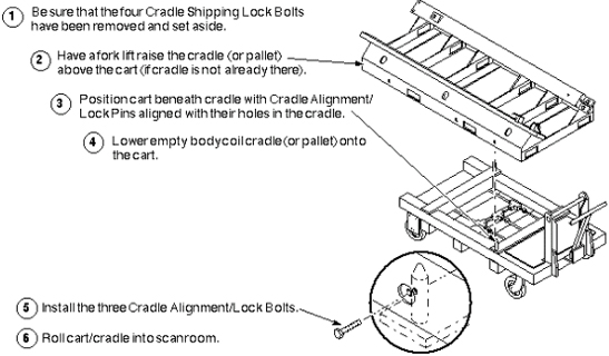
The next steps that prepare the empty cradle and cart to receive the failed body coil.
Figure 5. Prepare Cart and Cradle
- Refer to the illustration below to assemble the Roller Wheel
Assemblies and mount them on the failed coil.
Figure 6. Assembly and Mounting of Roller Wheel Assemblies
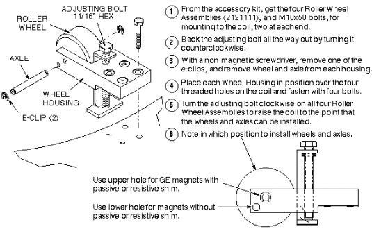 note:
note:Roller Wheel and Axle Positioning: In most cases, the axle/wheel combination is positioned in the higher of the two holes in the wheel housing (relative to a side view of the housing). The lower hole is used for placement of a body coil into a magnet without a resistive shim coil. (This type of magnet bore is larger in diameter so the body coil must sit higher in the bore.)
 |
3 Removing Failed Body Coil
Procedure
- warning
- Refer to the illustration to remove the rubber pads.
Figure 7. Removing Rubber Pads
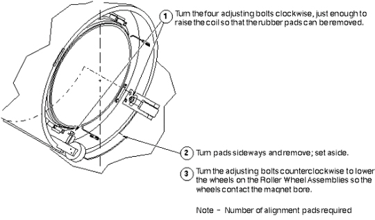 note:
note:Remember to use the saved rubber pads under the replacement coil. Refer to the Tools and Test Equipment section at the beginning of this procedure for an explanation of usage and part numbers.
- caution
- notice
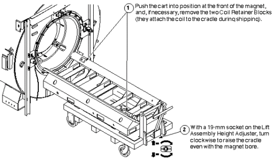
- Refer to the illustration below to place the empty cradle/cart
at the magnet, and load the failed coil onto it.
Figure 8. Positioning Empty Cradle and Cart
|
|
|
4 Coil Replacement in Mobile Sites
Procedure
- Overview
There are several possibilities for changing the gradient body coil in the various mobile configurations, and all differ significantly from fixed sites. The standard (or true) mobile van and the European version (called the Eurovan) require the coil to be replaced via the rear door. It would be ideal to make the change with the trailer backed up to a loading dock to avoid dealing with the rear steps of the van.
Gradient body coils in transportables and relocatables must be replaced via the overhead side door, but the floor must be temporarily reinforced with 3/4 in. plywood. Only the floor immediately below the magnet is strong enough to support the combined weight of the coil/cradle/cart combination. The patient lift in transportables cannot support this combination, so a lift truck must be used to place it inside the side door.
In some standard mobile vans (including Calumet Coach), the coil/cradle/cart combination can be wheeled through the rear door. In others, including Ellis and Watts and the Eurovans, a lift truck is needed to lift the replacement coil/cradle through the door. The limited space behind the magnet might make positioning the cart difficult, especially if you are not at a loading dock. It may be easier, in every instance, to skip using the cart and have the lift truck place the coil and cradle into the van.
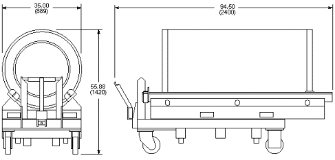
The dimensions to use as a guideline to determine whether or not to use the cart are: Total length of coil on cradle is 84 in. (2,134 mm) and total length of coil and cradle resting on the cart is 94.5 in. (2,400 mm). For additional dimensions, refer to the illustration below.
Figure 9. Gradient Coil, Cradle and Cart Dimensions
- notice
- Lift Truck Requirements for Failed Gradient Body Coil Removal
The fork lift truck used for this procedure should be rated for 6,000 pounds (2,700 kg) and should be capable of lateral movement of the forks: left to right and forward and reverse. It should also be able to tilt the forks up and down for the ease of properly aligning the replacement coil for movement into the bore.
- Preparing Lift Truck Aid
It will be easier for the lift truck driver, and more efficient for the whole operation, if some wood Is stacked up against the rear face of the magnet. This provides a place for the driver to rest the far end of the crate (still on the forks, of course). Take 30-inch minimum length pieces and stack them horizontally to a height of approximately 21 inches. Suggestion is to use two pieces of 8 in. x 8 in. wood and three pieces of 2 in. x 6 in. or 2 in. x 4 in. wood. Refer to the illustration below for stacking method.
Figure 10. Stacking Wood to Support Coil and Cradle
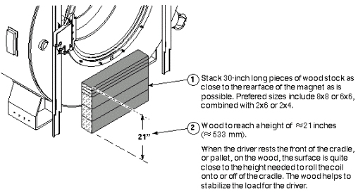 note:
note:When the driver rests the front edge of the cradle or wooden pallet on the wood, the surface of the cradle or pallet that the coil rests on should be close to the correct height for moving coils in and out of the bore. The wood helps stabilize the far end of the forks and their load.
- Lifting Coil Load
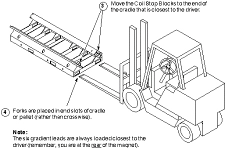
- This illustrates how to prepare the lift truck for changing
gradient coils in a mobile unit.
Figure 11. Acquiring Empty Cradle
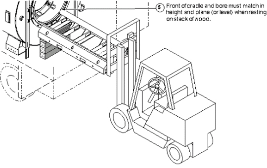
- This illustrates placement of the wood stack against the magnet
bore.
Figure 12. Supporting Empty Cradle with Wood Stack
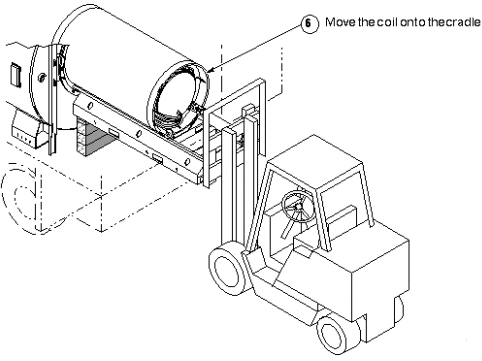
- The illustration below demonstrates how to move the coil onto
the cradle.
Figure 13. Rolling Failed Coil onto Cradle
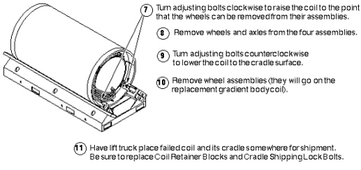
- Refer to the illustration below to prepare the failed coil for
return shipment.
Figure 14. Preparing Failed Coil for Return Shipment
- This illustrates how to prepare the lift truck for changing
gradient coils in a mobile unit.
- Proceed to Gradient Coil Replacement Coil Installation.
|
5 Finalization
Finalization
No finalization steps.