Dual Table Alignment Procedure
Prerequisites
Overview
These procedures are applicable to the following table products:
-
Signa Lightweight Patient Transport Table
-
Signa Oncology Patient Transport Table Option
-
Signa OR-Compatible Patient Transport Table Option
The alignment procedure requires:
-
One person for a Signa Lightweight Patient Transport Table
-
Two people for a Signa Oncology or Signa OR-Compatible Patient Transport Table Option
Procedure
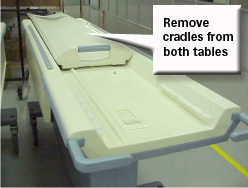
- Remove the cradle from both tables, see Removing Cradle Assembly. Step 2Figure 1.
Figure 1. REMOVE CRADLES FROM TABLES
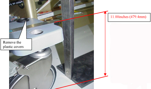
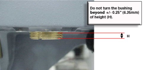
- Remove the plastic covers from the castings. Figure 2.
Figure 2. CASTER COVER AND HEIGHT
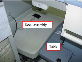
- Center the dock assembly with the bridge, at the front of the
magnet "Loosely attach the Dock assembly to the front of the magnet.
Do not secure the Dock to the magnet or floor. Centering will be
accomplished in Step 6." Figure 3.
Figure 3. ATTACH TABLE DOCK
 warning
- warning
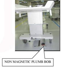
- Center the Dock assembly by using a Plumb Bob (Non magnetic
material). Figure 4.
Figure 4. CENTER THE TABLE
- Use the ¾” socket to adjust both front casters of table such that the top of the casting above the wheel is 11.00 (279.4mm) inches from the floor. Figure 2
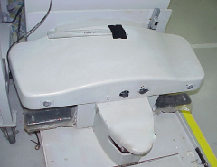
- Position the table to the dock, taking care not to move the
dock. DO NOT actuate the docking pedal. Figure 5.
Figure 5. DOCK TABLE
- notice
- With table #1 fully elevated, align the table top to the bridge
(which should be flush to 1 mm below the end bells) by adjusting the
front two casters, see Figure 6. Raise and lower the casters as needed while
keeping the center (between the two casters) close to the 11”
(279.4mm) height. REMEMBER, the casters should never be adjusted more
than +/- .25” (6.35mm) from the 11” (279.4mm) height. Figure 7. (Adjusting the high side down and the low side up by the same
amount ensures the dock center will stay aligned with the Patient
Transport docking mechanism.)
Figure 6. ALIGNING PATIENT TRANSPORT SURFACE TO BRIDGE
Figure 7. CASTER ADJUSTMENT WARNING
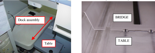
- Move the table and dock left or right until the table rail and
the bridge rail are in alignment. See Figure 8.
Figure 8. ALIGN BRIDGE AND CRADLE
- warning
- warning
- Place a mark on the floor adjacent to the side of the dock. (tape)
- Repeat stepsStep 6 toStep 9 for table #2 and then continue with Step 10.a.
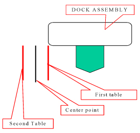
- Mark the center point between the 2 marks. Figure 9.
- Shift the dock assembly to align with the center point mark.
Figure 9. EXAMPLE OF RESULTS FROM THROUGH
- Secure the dock assembly in position.
- Complete the final lateral alignment by adjusting the front two casters if necessary. Raise and lower the casters as needed while keeping the center (between the two casters) close to the 11” (279.4mm) height. REMEMBER, the casters should not be adjusted more than +/- .25” (6.35mm). Figure 7.
- Tighten the Bushing Screw at on each caster.
 |
 |
|
|
Finalization
No finalization steps.