Dock Centering
Prerequisites
This procedure provides the Longitudinal Adjustment (in and out), and the Lateral Adjustment (left to right) to center the dock. For proper Patient Transport docking, the dock assembly must be adjusted to meet two criteria:
-
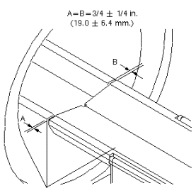
Gap between patient transport top and front of Magnet Enclosure must be 3/4 ±1/4 inch (19.0 ±6.4 mm). This is to ensure that the gap is narrow enough so UP Limit Sensor operates properly.
-
Dock assembly must be square to the bridge, so axis of cradle travel is the same for both patient transport and bridge.
1 Longitudinal Adjustment (In and Out)
Procedure
- With the patient transport docked, measure the distance from
the patient transport top to the front end bell. (See Figure 1.) Dimensions A and B should be 3/4 ±1/4 inch (19.0 ±6.4
mm) and equal to each other so the patient transport top is colinear
with the bridge.
Figure 1. Table Docking Measurement for Dock
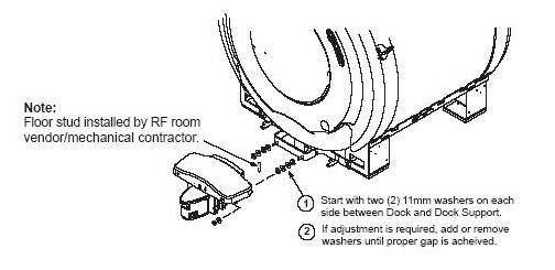
- If adjustment is required, add or remove washers until the proper
gap is achieved. (See Figure 2.)
Figure 2. Dock Positioning Adjustment
2 Lateral Adjustment (Left to Right)
Procedure
- Raise table to maximum height using the UP foot pedal.
- Dock the Patient Transport.
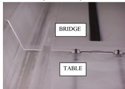
- Check the alignment of the Patient Transport against the bridge.
The guide rail down the length of Patient Transport top should match
the guide rail down the length of bridge. (See Figure 3.) For left-to-right only: Height is adjusted using theTable Top
Height Adjustment procedure.
Figure 3. Aligning Guide Rails
- If adjustment is required:
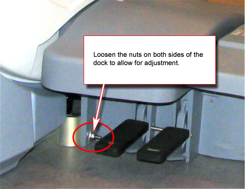
- Loosen the screws mounting the dock bracket to the magnet and the cover support brackets to dock bracket, and loosen the nuts mounting the dock to the dock bracket. (See Figure 4.)
- Move dock to proper position so guide rails line up. Lift the dock bracket slightly off the ground (approximately 1 mm) and tighten all fasteners.
Figure 4. Dock Positioning Adjustment
Finalization
No finalization steps.