Cradle Home Sensor
Prerequisites
Procedure
- System Power must be turned OFF. Refer to Lockout / Tagout for System Cabinet PDU Main Breaker..
- Disconnect the Table from MR Magnet for the easy operation. Refer to TAKE TABLE OUT FROM THE MAGNET ROOM.
- Remove the right top cover from the table. Refer to SCISSOR COVERS.
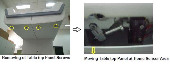
- Remove the right panel screws and remove the right Panel to
access to the Home Sensor.
Figure 1. Remove the right panel screws and the right Panel
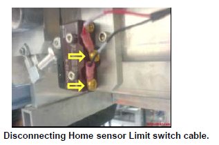
- Disconnect the Limit switch connection cable carefully.
Figure 2. Disconnecting Home Sensor Limit switch cable
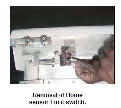
- Remove the Limit switch mounting screws, then the Limit switch.
Figure 3. Remove the Limit switch
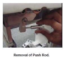
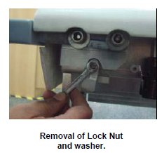
- Remove the Lock nut of the Push rod, and then remove the Push
rod.
Figure 4. Remove the Push rod
- Remove the Limit switch Dog nut, and then remove the washer
and Limit switch Dog.
Figure 5. Remove Limit switch Dog
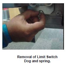
- Remove the Limit switch dog and the spring from the Table Top.
Figure 6. Remove the Limit switch dog and the spring
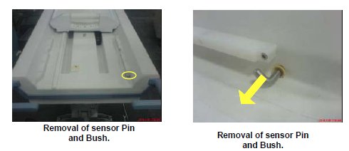
- Remove the Sensor Pin, Circlip and the Flange bush from the
other side of the Tabletop.
Figure 7. Remove the Sensor Pin, Circlip and the Flange bush
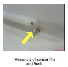
- Now take the parts from the New Home sensor Kit, Assemble the
Sensor rod in to the Bush, and insert the circlip to sensor Rod.
Figure 8. Assemble the Sensor rod in to the Bush
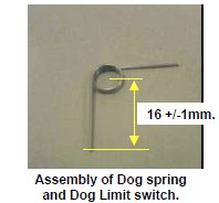
- Take the spring from the Kit; ensure that the lengths of the
legs are cut as per drawing. If not, Cut it to the Drawing size.
Figure 9. Spring
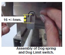
- Insert the spring into the Limit switch dog, assemble to the
Sensor rod on the other side of the Table Top.
Figure 10. Insert the spring into the Limit switch dog
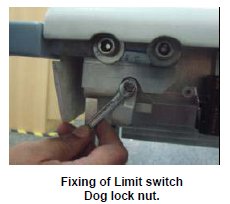
- Fix the washer and lock nut to the Sensor pin locking the Switch
Dog. Ensure spring action of the Switch Dog by actuating it.
Figure 11. Fix Limit switch dock lock nut
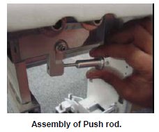
- Fix the Push rod and the Lock nut of the Push rod to the Dog
Switch.
Figure 12. Fix the Push rod
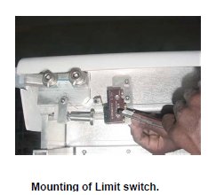
- Fix the Limit switch with the help of mounting screws.
Figure 13. Fix the Limit switch
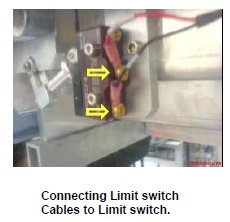
- Connect the sensor cables properly with the Limit switch.
Figure 14. Mounting Limit switch
- Move the Fixed Table and install to Dock Frame.
- Connect the Cables to the MR Gantry.
Finalization
- Turn the system power ON. Refer to Lockout / Tagout for System Cabinet PDU Main Breaker.
- Level the Table and perform Height Adjustment. Refer to LEVELING FIXED TABLE and TOP HEIGHT ADJUSTMENT.
- Fix the FRP Covers of the Table.
- Perform CRADLE HOME SENSOR CHECK .
- Check the Table Function. Refer to TABLE CHECKS AFTER INSTALLATION .
- Perform Express Coil MCQA Test to check that the PA coil cable is properly connected.