- id_12373821
- Version: 1.5
- Date: Jul 5, 2019 6:08:29 PM
XRMB Cable Busbar Replacement
Prerequisites
| Required persons | Preliminary requirements | Procedure | Finalization |
|---|---|---|---|
| 2 | 3 hours | 5 hours | 3-4 hours hours |
| Item | Quantity | Effectivity | Part number | Manufacturer |
|---|---|---|---|---|
| PPE: non-magnetic safety shoes, safety glasses, and gloves | 1 | - | - | - |
| Arc Flash PPE | 1 | - | - | - |
| Non-magnetic Torque Wrench | 1 | - |
5534134 or 5537507 |
- |
| Non-Magnetic Tools | 1 | - |
5112581 |
- |
| Item | Quantity | Effectivity | Part number | Manufacturer |
|---|---|---|---|---|
| Blue Loctite 243 (check expiration date) | 1 | - |
5415261-2 |
- |
| Alcohol wipes | As needed | - | - | - |
| Scotch Brite pad | 1 | - | - | - |
| Black Sharpie pen | 1 | - | - | - |
| Nylon Tie Wraps | As needed | - | - | - |
| Item | Quantity | Effectivity | Part number | Manufacturer |
|---|---|---|---|---|
| XRMB Cable Busbar | 1 | - |
See FRU Manual |
- |
| Busbar Step Gauge (part of FRU) | 1 | - |
See FRU Manual |
- |
|
| Condition | Reference | Effectivity |
|---|---|---|
|
At least one person performing this procedure must have taken training course GEHC-TECH-AMOL-CT530-01_CURR. |
- | - |
Overview
This procedure describes the replacement or installation process of the eXtreme Resonance Module Revision B (XRMB) busbar (cable version) in the MR450 1.5T magnet.
Getting Started
Procedure
- Order the non-magnetic torque wrench before starting this procedure.
 caution
- Follow all safety lockout/tagout procedures.
-
Perform LOTO on the PGR PDU/gradient subsystem. See the MR Service Safety Manual, PN 5452735.
-
Perform LOTO on the RF amplifier and PEN cabinet (magnet room electronics). See the MR Service Safety Manual, PN 5452735.
note:Do not shut down the cryogen cooling system.
-
- Remove the patient bridge. See Bridge and Longitudinal Drive Belt Replacement.
- Remove the magnet enclosure rear end bell. See Rear End Bell Removal and Installation.
- Move the rear pedestal away from the magnet.note:
There should be two feet of cable in the service loop. This excess cable allows the rear pedestal to be moved back without disconnecting cables; however, it is possible that some cables may need to be disconnected.
 |
Remove XRMB Gradient Busbar Cables
Procedure
- Remove the two M8x12 mm stainless steel screws and remove the
XRMB busbar safety cover. Do not discard the white flame-retardant
material or the fasteners.
Figure 1. Busbar Safety Cover
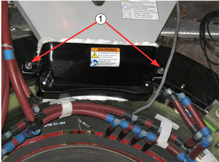
Item Description 1 M8x12 stainless steel screws and M8 nylon flat washers - Remove the six nuts and Nord-Lock washers that are securing
the busbar lugs.
Discard the Nord-Lock washers and stainless steel flange nuts.
Figure 2. Removing Nuts and Nord-Lock Washers
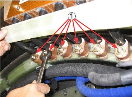
Item Description 1 Six (6) stainless steel nuts and Nord-Lock washers note:DO NOT remove the clamps on the busbar leads.
- At the top of the busbar, remove the five M6 stainless steel
screws and the clear plastic cover.
Figure 3. Fasteners Holding Clear Plastic Cover
Item Description 1 Five stainless steel screws - Loosen the retainer blocks to allow slack in order to remove the gradient power terminals from the busbar.
- Remove the 12 stainless steel nuts and Nord-Lock washers securing
the gradient power cables to the busbar terminals.
Discard the stainless steel nuts and Nord-Lock washers.
Figure 4. Disconnecting Gradient Power Cables at Top of Busbar
Item Description 1 Twelve stainless steel nuts and Nord-Lock washers
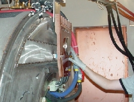
Remove Busbar
Procedure
- Remove the four brass nuts, G10 flat washer, and rubber isolators
securing the busbar assembly to the magnet. Remove the tie-wraps securing
the manifold hoses to the busbar. The busbar may look like either
of the next two pictures.
Figure 5. Busbar Mounting Points
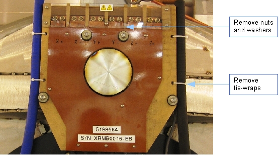
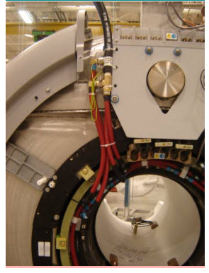
Figure 6. Busbar Removed
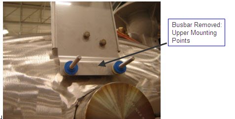
- The busbar can now be removed from the magnet.
Install New XRMB Busbar
Procedure
- Inspect the gradient terminal lugs for threadlocker residue.
Clean with a nonmetallic brush and wipe the threads clean with alcohol.
Use a clean nut to check the threads. The nut should thread freely with no high resistance points. Repeat procedure on each lug as required.
- Install two M10 x 150 mounting studs 5324035-6 into the two lower mounting points using Loctite 242.
Figure 7. Lower Mounting Studs
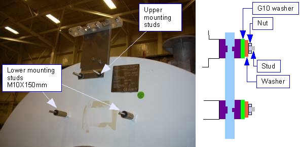
- At each of the lower mounting studs, install one phenolic spacer 5177686 and one rubber washer 46-294167P96 with the pilot step facing outward.
- At each of the upper mounting studs, install one rubber isolator as shown in Figure 7.
- Remove the new busbar assembly from the busbar shipping crate.note:
Before installing the replacement busbar, inspect the surface that connects the gradient coil and cables for oxidation. If the surface is oxidized, clean the surface.
DO NOT lift the busbar assembly by holding the leads.
- Align the six busbar lugs with the XRMB coil terminal studs, and smoothly push the lugs onto the terminal studs. Meanwhile, slide the busbar assembly onto the four busbar support studs Figure 9.
- If absent, install the grounding cable, PN 5189441-2.
Figure 8. Placing Busbar Lugs on Terminal Studs
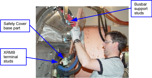
Figure 9. Placing Busbar on Support Studs
- Ensure that the loose ends of the grounding cables can be accessed
when the busbar is replaced.
Figure 10. Accessible Grounding Cables
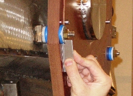
- After the busbar is mounted, place one rubber isolator, one large G10 flat washer (32 mm OD, 5268439), one M10 x 24 mm washer (5146169), and one brass nut at each of the four mounting studs. The step of the rubber isolator faces inward.
- Gradually tighten the four brass nuts until the height of the
G10 washer surface (front side) reaches 7.2 mm. Use the step gauge
(part of the busbar FRU) to verify the height of the G10 washer. Verify
the busbar lugs are not hung up on the stud threads.note:
The step gauge is required to prevent stress fractures on the gradient lead terminals.
Figure 11. Checking G10 Washer Height Using Step Gauge
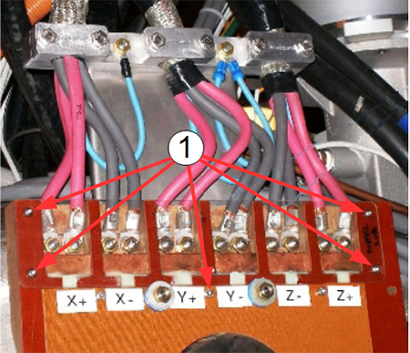
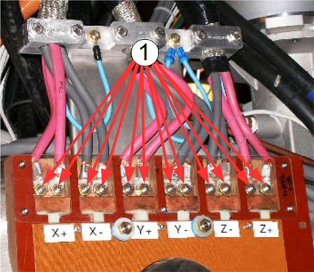
Install Busbar Cables
Procedure
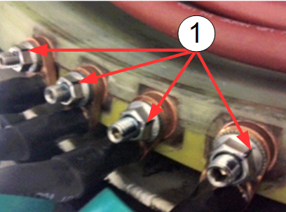
- At the top of the busbar, connect the 12 gradient power cables
to the busbar terminals and secure them using one nut and one Nord-Lock
washer at each of the terminals. Use the torque wrench to tighten
the nuts on the top of the busbar to 25 foot-pounds (33.9 Nm). Read
the following steps prior to using the torque wrench.
Figure 12. Connecting Gradient Power Cables on Top of Gradient Coil
- Place a new Nord-Lock washer over each stud.note:
Observe the following:
-
Always use the new Nord-Lock washers that come with the FRU package. DO NOT reuse the old Nord-Lock washers.
-
Nord-Lock washers consist of two pieces, which are generally glued together. Always use a complete set with two pieces joined together in correct orientation. DO NOT use a separated single piece. If the Nord-Lock washers are separated, or the nuts are untightened, discard the washers and replace them with new Nord-Lock washers only. If new Nord-Lock washers are not available, contact the online center for further instructions.
-
Always shake Loctite bottle before use.
Figure 13. Nord-Lock Washers
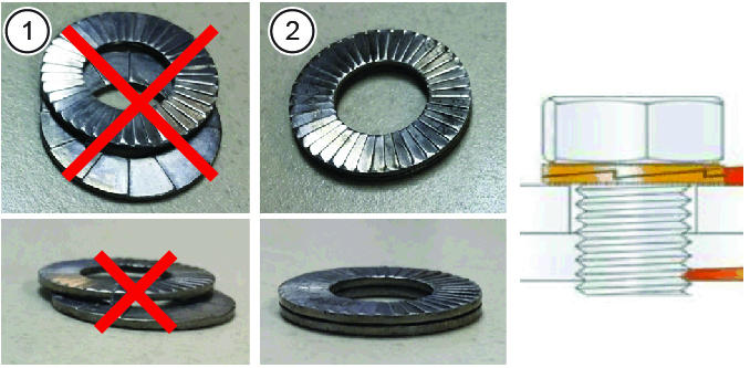
1 Wrong (do not use separated washers) 2 Correct -
- Put two drops of Loctite 243 on the exposed thread of the terminal
stud.
Do not get Loctite on the Nord-Lock washer.
Discard the old stainless steel nuts and washers.
Figure 14. Loctite on Stud
Item Description 1 Bus bar terminal lug 2 Loctite on stud 3 Nord-Lock washer (installed after lug) - Hand-tighten the new stainless steel nut on the stud.
- danger
- notice
- notice
- notice
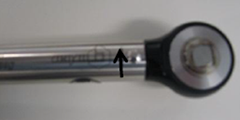
- Set the torque wrench to 25 foot-pounds (33.9 Nm). Install 15
mm socket on the extension.note:
Make sure that the arrow on the torque wrench is visible. If the arrow is not visible, the torque wrench will not “click” when the proper torque is reached.
Figure 15. Arrow on Non-magnetic Torque Wrench
- Torque the nut in the direction of the arrow until the torque
wrench reaches the break point.note:
Proper torque to the nuts holding the busbar lugs is critical to the long-term stability of the gradient subsystem.
- Using a Sharpie pen, place a line from the base of the stud
to the nut.
Figure 16. Stud and Nut Marked to Show Torque Position
- Repeat this for all the stainless steel flanged nuts.
- Perform a second torque operation at each nut to confirm the proper torque of the nut. (Twice for each nut.)
- If the nut has moved more than one flat from the original position, you must re-torque for a third time.
- If re-torqueing is necessary, remark the torque position (line) on the nut and stud.
- Secure the gradient cable guard (clear plastic cover) using five M6 stainless steel screws. See Figure 3.
- Install the busbar cable terminal lugs on the lower portion of the busbar as shown in Figure 16.
- Install the safety cover and white flame retardant material.
- Inspect the flame-retardant material (white cloth) for tears or internal damage. Replace safety cover if liner is damage. See FRU list for part number.
- Confirm that the material extends just beyond the edge of the safety cover on all sides. See Figure 1.
- Inspect each M8x12 stainless steel screws and remove any old threadlocker residue with alcohol, as necessary.
- Apply one drop of Loctite to the thread of each M8x12 stainless steel screw.
- Tighten the two M8x12 mm stainless steel screws.
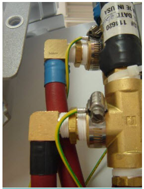
- Secure the manifold hoses to the busbar using nylon tie-wraps.
Inspect and ensure there is no contact between the safety covers and the manifold hoses.
- If the hoses on the left side of the busbar are uneven, use
a Push-Lok Hose, PN 5394470 to even the hoses.
Figure 17. Tie-Wrapping Manifold Hoses to Busbar and Applying Ground Wires
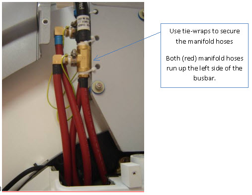
Figure 18. Applying Ground Wires by Hose Clamp to Manifold Fittings
Figure 19. Final Position of Manifold Hoses
|
 |
|
|
Finalization
Procedure
- Reposition the rear pedestal.
- Install the magnet enclosure rear end bell. See Rear End Bell Removal and Installation.
- Install the patient bridge. See Bridge and Longitudinal Drive Belt Replacement.
- Replace all covers that were previously removed.
- Remove lockout/tagout (LOTO) to the PGR PDU/gradient subsystem and the RF amplifier in the PEN cabinet. See the MR Service Safety Manual, PN 5452735.
- Execute DQA scan in all three planes to verify proper geometry. See DQA II Tool and Troubleshooting.