- id_12374913
- Version: 1.4
- Date: Jan 17, 2020 10:59:55 AM
Ground Resistance Checks
Prerequisites
| Required persons | Preliminary requirements | Procedure | Finalization |
|---|---|---|---|
| 1 | Not Applicable | 60 minutes | 5 minutes |
| Item | Quantity | Effectivity | Part number | Manufacturer |
|---|---|---|---|---|
| Digital voltmeter (optional) | 1 | - | - | - |
| Bio-design MG5 meter (Microguard) with Milliohm Adapter | 1 | - |
46-194427P16 |
- |
| Dale 600 or 601 (120 VAC) or Dale 600E or 601E (220 VAC) Safety Analyzer | 1 | - |
600/601: 46-285647P1 or 46-328406G1 600E/601E: 46-285647P14 or 46-328406G2 |
- |
| Fluke ESA612 Electrical Safety Analyzer | 1 | - |
5453348 |
- |
| Personal Lock | 2 | - |
46-194427P320 |
- |
| Red Warning LOTO Tag | 2 | - |
46-194427P322 |
- |
| Multi-locking Device (If multiple service people) | 1 | - |
46-194427P313 |
- |
| Item | Quantity | Effectivity | Part number | Manufacturer |
|---|---|---|---|---|
| Ground Wires | as needed | - | - | - |
|
| Condition | Reference | Effectivity |
|---|---|---|
|
Any required electrical code inspection |
- | - |
|
Installation of the facility disconnect device |
- | - |
|
EMERGENCY OFF wiring |
- | - |
|
PDU primary wiring |
- | - |
|
PDU subsystem power cables |
- | - |
|
Refer to the power cable installation instructions in the System Installation Manual. |
- | - |
|
No hard wired signal cables connected to any subsystem cabinets. Fiber optic cables may be connected and not impact this check. |
- | - |
Overview
This document contains a method for measuring ground resistance using different brands of safety analyzers. Only one of the safety analyzers listed in Tools and Test Equipment is required for this procedure.
Ground resistance checks are required at every site. Ground Leakage Test is only performed when local regulation or code requires it.
Ground resistance checks are required for the following cabinets.
-
PEN cabinet
-
Host GOC cabinet
-
HEC cabinet
-
Secondary PEN panel or SPW
-
Brainwave cabinet (optional equipment)
-
MNS cabinet (optional equipment)
Review and understand the required conditions before beginning this procedure.
| If you are using | Go to Section |
| Microguard | Ground Resistance Checks Using Microguard |
| Dale 600/600E or 601/601E safety analyzer | Ground Resistance Checks Using Dale (Sites Equipped with Dale 600, 600E, 601, or 601E Safety Analyzer) |
| Fluke ESA612 safety analyzer | Ground Resistance Checks Using Fluke ESA612 |
Ground Resistance Checks Using Microguard
Procedure
 danger
- Perform LOTO on the MDP. See the MR Service Safety Manual, PN 5452735.
- Notify all Field Service Engineers working at the site that the MDP is being shut off, locked out, and tagged out.
- Locate and shut off the MDP which supplies power to the PDU and HEC.
- Check that the MDP and PDU indicator lights are off, and that the power switches are inactive.
- With a digital voltmeter (DVM), check that all energy has dissipated.
- Plug the milliohm adaptor module into the power outlet of the
Microguard.
Figure 1. Microguard Connections
 note:
note:Because the Microguard is being used solely as a voltmeter in this application, any other meter capable of resolving 0.1 millivolts can be substituted in the next step. Meters other than the Microguard are currently in use. Refer to the appropriate tool catalog for further information.
- Attach the Microguard red and black leads to the meter posts of the milliohm module.
- Set the Microguard Patient Lead Tester switch to All Other Tests.
- Set the Microguard Selector switch to 20 Microamps/Millivolts.
- Set the Microguard Input switch to Red and Black Probes.
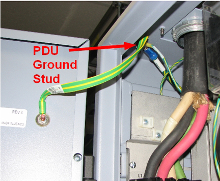
- Attach the Kelvin leads. Connect one lead to the PDU ground
located on the upper left side of the PGR cabinet and the other lead
to the frame of the subsystem cabinet under test.
Figure 2. PDU Ground Stud
- The meter reads voltage across ground resistance in millivolts. To obtain the resistance in milliohms, multiply the meter reading by 2.
- Verify that the measured resistance is less than 100 milliohms (corresponding to a meter reading of 50 millivolts). If this fails, recheck and reposition the lead connections and inspect the power cable connection from PGR J16 to the PEN cabinet. If the reading fails, add an additional ground cable to the cabinet that is failing.
- Perform Step 11 through Step 13 for the remaining
cabinets:
-
Host GOC cabinet
-
HEC cabinet
-
Secondary PEN panel or SPW
-
Brainwave cabinet (optional equipment)
-
MNS cabinet (optional equipment)
note:Additional cable may be needed to measure ground resistance to the selected cabinet, because the distance between the PGR and the selected cabinet can vary.
-
- Restore the system:
-
Turn the Microguard power off.
-
Remove the leads and the milliohm adapter from the Microguard.
-
Close all subsystem cabinets and the PGR cabinet.
-
Ground Resistance Checks Using Dale (Sites Equipped with Dale 600, 600E, 601, or 601E Safety Analyzer)
Procedure
- danger
- Ensure that no power is applied to the MDP. See the MR Service Safety Manual, PN 5452735.
- Notify all Field Service Engineers working at the site that the MDP is being shut off, locked out, and tagged out.
- Locate and shut off the MDP which supplies power to the PDU and HEC.
- Check that the MDP and PDU indicator lights are off, and that the power switches are inactive.
- With a digital voltmeter (DVM), check that all energy has dissipated.
- Connect one clamp-type lead to the EXTERNAL jack on the top of the Dale safety analyzer. Connect the other clamp-type
lead to the CHASSIS jack on the top of the
Dale safety analyzer.
Figure 3. Top of Dale Safety Analyzer
- On the Dale safety analyzer, set the main selector switch to W - RESISTANCE.
Figure 4. Dale Safety Analyzer
- Plug the Dale safety analyzer into an AC outlet.
- On the Dale safety analyzer, verify that the two OK LEDs light up to indicate that the AC outlet is properly wired.
- With the leads not touching each other, the display should read 1.00. With the leads touching (copper to copper), the display should read 0.00 to 0.02.
- Attach the leads. Connect one lead to the PDU ground located
on the upper left side of the PGR cabinet (see Figure 2) and the other
lead to the bare frame of the subsystem cabinet under test.
Figure 5. Dale Safety Analyzer Connections
 note:
note:The Dale safety analyzer reads resistance in ohms. For example, a reading of 0.50 equals 500 milliohms.
- Verify that the measured resistance is less than 100 milliohms (corresponding to a meter reading of 50 millivolts). If this fails, recheck and reposition the lead connections and inspect the power cable connection from PGR J16 to the PEN cabinet. If the reading fails, add an additional ground cable to the cabinet that is failing.
-
Perform Step 11 through Step 12 for the remaining
cabinets:
-
Host GOC cabinet
-
HEC cabinet
-
Secondary PEN panel or SPW
-
Brainwave cabinet (optional equipment)
-
MNS cabinet (optional equipment)
note:Additional cable may be needed to measure ground resistance to the selected cabinet, because the distance between the PGR and the selected cabinet can vary.
-
- Restore the system:
- Unplug the Dale safety analyzer from the AC outlet.
- Remove the leads from the Dale safety analyzer.
- Close all subsystem cabinets and the PGR cabinet.
Ground Resistance Checks Using Fluke ESA612
Procedure
- danger
- Ensure that no power is applied to the MDP. See the MR Service Safety Manual, PN 5452735.
- Notify all Field Service Engineers working at the site that the MDP is being shut off, locked out, and tagged out.
- Locate and shut off the MDP which supplies power to the PDU and HEC.
- Check that the MDP and PDU indicator lights are off, and the power switches are inactive.
- With a digital voltmeter (DVM), check that all energy has dissipated.
- note:Turn on the Fluke meter and select the point to point option on the meter.
At facilities with 110-120 VAC, a fault error may appear when you power the meter on. Press F4 OK to clear the error, and continue.
Figure 6. Fluke ESA612 Safety Analyzer
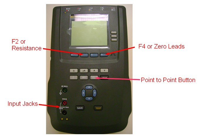
- Select resistance or F2.
- Attach the leads into the red and black input jackets and short the leads together.
- Select zero leads or F4.
- Connect one lead to the PDU ground located on the upper left side of the PGR cabinet (see Figure 2) and the other lead to the bare frame of the subsystem cabinet under test.
- Verify that the measured resistance is less than 100 milliohms. If this fails, recheck and reposition the lead connections and inspect the power cable connection from PGR J16 to the PEN cabinet. If the reading fails, add an additional ground cable to the cabinet that is failing.
- Repeat Step 10 through Step 11 for the remaining cabinets:
-
Host GOC cabinet
-
HEC cabinet
-
Secondary PEN panel or SPW
-
Brainwave cabinet (optional equipment)
-
MNS cabinet (optional equipment)
note:Additional cable may be needed to measure ground resistance to the selected cabinet, because the distance between the PGR and the selected cabinet can vary.
-
- Restore the system.
- Turn off the Fluke safety analyzer.
- Remove the leads from the analyzer.
- Close all subsystem cabinets and the PGR cabinet.
Finalization
Finalization
-
Remove LOTO from the MDP and restore power. See the MR Service Safety Manual, PN 5452735.
-
Perform a Check Scan.