- id_12373501
- Version: 1.8
- Date: Jan 17, 2020 11:01:10 AM
Ground Leakage Current Test
Prerequisites
| Required persons | Preliminary requirements | Procedure | Finalization |
|---|---|---|---|
| 2 | Not Applicable minutes | 180 minutes | 5 minutes |
| Item | Quantity | Effectivity | Part number | Manufacturer |
|---|---|---|---|---|
| Dale 600 or 601 (120 VAC) or Dale 600E or 601E (220 VAC) Safety Analyzer | 1 | - |
600/601: 46-285647P1 or 46-328406G1; 600E/601E: 46-285647P14 or 46-328406G2 |
- |
| Fluke ESA612 Electrical Safety Analyzer | 1 | - |
5453348 |
- |
| Hazard Class 2 Personal Protective Equipment (PPE) | 2 | - |
|
- |
| Digital Volt Meter (DVM) with Jumper Leads | 1 | - |
46-194427P284 |
- |
| Personal Lock | 2 | - |
46-194427P320 |
- |
| Red Warning LOTO Tag | 2 | - |
46-194427P322 |
- |
| Multi-Locking Device (for multiple service technicians) | 1 | - |
46-194427P313 |
- |
|
| Condition | Reference | Effectivity |
|---|---|---|
|
All personnel performing this procedure must have completed proper electrical hazard training courses. |
- | - |
|
Verify Ground Resistance Checks are completed and passed. |
- | - |
|
Confirm that all cables are installed correctly. |
- | - |
|
Confirm that the main disconnect of the PDU is ON. |
- | - |
|
Confirm that all subsystem cabinet circuit breakers and subsystem power switches are ON. |
- | - |
|
Confirm that Hazard Class 2 Personal Protective Equipment (PPE) is available. |
- | - |
Overview
Before performing this procedure, you must have completed proper electrical hazard training courses, including:
-
Power and Grounding Audit (GEHC-TECH-AMOL-CM9010) or equivalent
-
Electrical Safety Authorized Course (GE-EHS-280) or equivalent
This document contains a method for measuring ground leakage current using different brands of safety analyzers. Only one of the safety analyzers listed in Tools and Test Equipment is required for this procedure.
Review and understand all required conditions before beginning this procedure.
|
Ground Leakage Current Test
The following table highlights the tasks in the Ground Leakage Current Test procedure in the order that they should be performed. Some equipment listed are optional equipment and are only tested if on the system.
| Task to be performed | Go to section | Required/Optional |
| Record safety analyzer data and link to form | Recording Readings | Required |
| Set up safety analyzer | Setting Up Safety Analyzer | Required |
| Perform LOTO | Performing LOTO | Required |
| Locate ground wires in PGR cabinet | Locating Ground Wires at PGR Cabinet | Required |
| Test PEN cabinet | Testing PEN Cabinet | Required |
| Test Host GOC cabinet | Testing Host GOC Cabinet | Required |
| Test Brainwave cabinet | Testing Brainwave Cabinet (Optional Equipment) | Optional |
| Test MNS cabinet | Testing MNS Cabinet (Optional Equipment) | Optional |
| Restore system | Restoring System | Required |
| Finalization steps | End of document | Required |
Recording Readings
Because this procedure is performed only when local regulations or codes require it, the readings gathered during this procedure must be recorded for the local authority. A copy of the measurements should also be retained with the site documentation. Use the following tables to record your measurements. Mark any fields that are not applicable to the current location as “not applicable” or “N/A”. A PDF of this table is here: 4702021.pdf
| Safety Analyzer Information | ||
| Brand of Safety Analyzer | ||
| Safety Analyzer Model No. | ||
| Safety Analyzer Serial No. | ||
| Calibration Date | ||
| Date of Tests | ||
| Name of Tester (Printed) | ||
| Signature of Tester | ||
| DV Product Unit | Max Leakage Current | if < 5.0 mA, PASS |
| Pen Cabinet | ||
| Host Global Operator Console Cabinet | ||
| Brainwave Cabinet (Optional Equipment) | ||
| MNS Cabinet (Optional Equipment) | ||
Setting Up Safety Analyzer
Procedure
- Two types of safety analyzers are available. Use the instructions for the safety analyzer that is available.
- Set up the safety analyzer near the front of the PDU.
-
Using Dale Safety Analyzer:
- Connect one clamp-type lead to the EXTERNAL jack on the top of the Dale safety analyzer. Connect the other clamp-type lead to the CHASSIS jack on the top of the Dale safety analyzer.
- On the Dale safety analyzer, set the main selector switch to EXTERNAL.
Figure 1. Connections on Dale Safety Analyzer
-
Using Fluke ESA612 Safety Analyzer:
- note:Turn on the Fluke safety analyzer.
At facilities with 110-120 VAC, a fault error may appear when you power the meter on. Press F4 OK to clear the error, and continue.
Figure 2. Fluke ESA612 Electrical Safety Analyzer
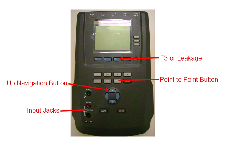
- Select the [point to point] button.
- Select the [F3 or Leakage] button.
- Select the [Up Arrow] once so that AC Only displays.
- Insert the leads into the input jacks.
- The safety analyzer is now set up with the two leads attached and ready to be connected to the PDU.
Performing LOTO
Procedure
- Properly shut down the system (if the host computer is up). Turn OFF all equipment.
- Confirm that all equipment is available to perform LOTO on the Main Disconnect Panel (MDP). See LOTO information in the MR Service Safety Manual, PN 5452735.
- Confirm that all circuit breakers on the front panel of the PDU are in OFF position (down).
- With a digital voltmeter (DVM), check that all energy has dissipated. Confirm that the PDU indicators lights are OFF.
Locating Ground Wires at PGR Cabinet
Procedure
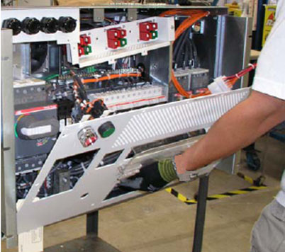
- Open the PDU front panel, but do not remove connector wiring
or the connectors, as specified in steps 1 to 4 in Section 4.1.2 of Teal PDU Service Guide.
-
The Teal PDU Service Guide (P/N 5140621) is for the PGR cabinet containing the XGD hardware.
-
The Teal PDU Service Guide (P/N 5343114) is for the PGR cabinet containing the XG2 hardware.
Figure 3. Removing PDU Cover
-
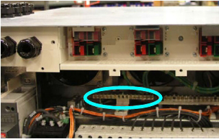
- Locate four green and yellow ground wires connecting to left
side of the PDU bus bar as shown in Figure 4. These wires
can be difficult to see. You may need to cut away some cable ties
and use a flashlight to locate them. Confirm by visual inspection
that each green and yellow wire traces back to one of 4 power cable
bundles and identify which green and yellow pair is associated with
which cabinet/circuit breaker combination:
-
Brainwave cabinet (optional equipment)–BRAINWAVE circuit breaker
-
MNS cabinet (optional equipment)–RF+MNS circuit breaker
-
PEN cabinet–PEN cabinet circuit breaker
-
Host Global Operator Console cabinet–HOST circuit breaker
Ground leads on the PDU busbar can be reached by opening the front cover of the PDU.
Figure 4. Location of PDU Busbar
-
- During the testing procedure for each cabinet, the following
general steps are performed.
- Remove the ground wire from the PDU busbar.
- Connect the ground wire of the cabinet being tested to the EXTERNAL clamp-type lead of the safety analyzer.
- notice
- Connect the CHASSIS clamp-type lead of the safety analyzer to the PDU ground busbar.

Testing PEN Cabinet
Procedure
- Remove all cables at the back and top of the PEN panel cabinet. Do NOT remove the power cable (J1).
- Disconnect the green and yellow ground wire associated with the 3-phase hot leads to PEN cabinet circuit breaker from the PDU busbar and attach it to the EXTERNAL clamp-type lead on the safety analyzer.
 warning
- Connect the chassis clamp-type lead on the safety analyzer to the PDU ground busbar.
- Remove LOTO and turn on the facility disconnect. See LOTO information in the MR Service Safety Manual, PN 5452735.
- Turn on the main power switch on the PDU.
Figure 5. Main PDU Circuit Breaker
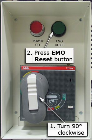
- Turn on the PEN cabinet circuit breaker for the PEN cabinet.note:
On the Dale safety analyzer, 500 mV corresponds to 500 µA (0.5 mA) of leakage current.
- Record the ground leakage current. (See Recording Readings.)
- Confirm that the leakage current is less than 5000 µA (5.000 mA) and record this value. Proceed to Step 8.
- If the leakage current is greater than 5000 µA (5.000
mA), a serious leakage current problem exists that must be corrected.note:
The Dale safety analyzer can be affected by high magnetic fields. Try relocating the position of the unit a few inches up, down, right, or left to see if the reading changes. No change in the reading indicates it is accurate.
If the leakage current is more than 5000 µA (5.000 mA): Do not proceed with further testing until leakage current is less than 5000 µA (5.000 mA).
Proceed directly to remove power at the MDP and LOTO the MDP. See LOTO information in the MR Service Safety Manual, PN 5452735.
Check all system ground connections to troubleshoot and isolate source of leakage. Do not proceed with further testing until the cause for the leakage is found and fixed. Because a failing ground leak current check is unusual, seek technical support from the local power and grounding expert before proceeding with any actions.
- Turn the PEN cabinet circuit breaker to OFF to remove power from the PEN cabinet.
- Perform LOTO on the MDP. See LOTO information in the MR Service Safety Manual, PN 5452735.
- With a digital voltmeter (DVM), check that all energy has dissipated. Confirm that the PDU indicators lights are OFF.
- Reconnect the green and yellow ground wire to the PDU busbar and confirm a tight connection.
 |
Testing Host GOC Cabinet
Procedure
- Remove all cables at the back and the top of the Host GOC cabinet. Do NOT remove the power cable (J1).
- Disconnect the green and yellow ground wire associated with the HOST circuit breaker from the PDU busbar and attach it to the EXTERNAL clamp-type lead on the safety analyzer.
- warning
- Connect the chassis clamp-type lead on the safety analyzer to the PDU ground busbar.
- Remove LOTO and turn on the facility disconnect. See LOTO information in the MR Service Safety Manual, PN 5452735.
- Turn on the main power switch on the PDU.
Figure 6. Main PDU Circuit Breaker
- Turn on the HOST current breaker for the GOC.note:
On the Dale safety analyzer, 500 mV corresponds to 500 µA (0.5 mA) of leakage current.
- Record the ground leakage current. (See Recording Readings.)
- Confirm that the leakage current is less than 5000 µA (5.000 mA) and record this value. Proceed to Step 8
- If the leakage current is greater than 5000 µA (5.000
mA), a serious leakage current problem exists that must be corrected.note:
The Dale safety analyzer can be affected by high magnetic fields. Try relocating the position of the unit a few inches up, down, right, or left to see if the reading changes. No change in the reading indicates it is accurate.
If the leakage current is more than 5000 µA (5.000 mA): Do not proceed with further testing until leakage current is less than 5000 µA (5.000 mA).
Proceed directly to remove power at the MDP and LOTO the MDP. See LOTO information in the MR Service Safety Manual, PN 5452735.
Check all system ground connections to troubleshoot and isolate source of leakage. Do not proceed with further testing until the cause for the leakage is found and fixed. Because a failing ground leak current check is unusual, seek technical support from the local power and grounding expert before proceeding with any actions.
- Turn the HOST circuit breaker to OFF to remove power from the GOC.
- Perform LOTO on the MDP. See LOTO information in the MR Service Safety Manual, PN 5452735.
- With a digital voltmeter (DVM), check that all energy has dissipated. Confirm that the PDU indicators lights are OFF.
- Reconnect the green and yellow ground wire to the PDU busbar and confirm a tight connection.
|
Testing Brainwave Cabinet (Optional Equipment)
If the Brainwave option is installed, follow these steps to test the ground leakage current. If it is not installed, proceed to Restoring System
Procedure
- Remove all cables from the back and top of the Brainwave cabinet. Do NOT remove the power cable.
- Disconnect the green and yellow ground wire associated with the BRAINWAVE circuit breaker from the PDU busbar and attach it to the EXTERNAL clamp-type lead on the safety analyzer.
- warning
- Connect the chassis clamp-type lead on the safety analyzer to the PDU ground busbar.
- Remove LOTO and turn on the facility disconnect. See LOTO information in the MR Service Safety Manual, PN 5452735.
- Turn on the main power switch on the PDU.
Figure 7. Main PDU Circuit Breaker
- Turn on the BRAINWAVE circuit breaker for the Brainwave cabinet.note:
On the Dale safety analyzer, 500 mV corresponds to 500 µA (0.5 mA) of leakage current.
- Record the ground leakage current. (See Recording Readings).
- Confirm that the leakage current is less than 5000 µA (5.000 mA) and record this value. Proceed to Step 8.
- If the leakage current is greater than 5000 µA (5.000
mA), a serious leakage current problem exists that must be corrected.note:
The Dale safety analyzer can be affected by high magnetic fields. Try relocating the position of the unit a few inches up, down, right, or left to see if the reading changes. No change in the reading indicates it is accurate.
If the leakage current is more than 5000 µA (5.000 mA): Do not proceed with further testing until leakage current is less than 5000 µA (5.000 mA).
Proceed directly to remove power at the MDP and LOTO the MDP. See LOTO information in the MR Service Safety Manual, PN 5452735.
Check all system ground connections to troubleshoot and isolate source of leakage. Do not proceed with further testing until the cause for the leakage is found and fixed. Because a failing ground leak current check is unusual, seek technical support from the local power and grounding expert before proceeding with any actions.
- Turn the BRAINWAVE circuit breaker to OFF to remove power from the Brainwave cabinet.
- Perform LOTO on the MDP. See LOTO information in the MR Service Safety Manual, PN 5452735.
- With a digital voltmeter (DVM), check that all energy has dissipated. Confirm that the PDU indicators lights are OFF.
- Reconnect the green and yellow ground wire to the PDU busbar and confirm a tight connection.
|
Testing MNS Cabinet (Optional Equipment)
If MNS option is installed, follow these steps to test the ground leakage current. If it is not installed, proceed to Restoring System
Procedure
- Slide the RF amplifier out from the PGR cabinet. For details, see the RF amplifier replacement procedure for the system being tested. The amplifier does not need to be removed.
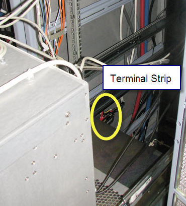
- Access the MNS terminal strip, located in the center of the
PGR cabinet.
Figure 8. Terminal Strip Location
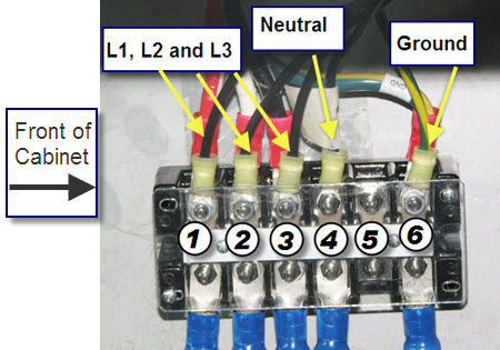
- Install the safety analyzer between terminal 6 and the MNS cable
that is connected to terminal G (see item 6 in the following illustration).
Figure 9. Terminal Strip Connections
- Remove LOTO and turn on the facility disconnect. See LOTO information in the MR Service Safety Manual, PN 5452735.
- Turn on the main power switch on the PDU.
Figure 10. Main PDU Circuit Breaker
- Turn on the RF+MNS circuit breaker.
- Record the ground leakage current.
- Confirm that the leakage current is less than 5000 µA (5,000 mA) and record this value. Proceed to Step 8.
- If the leakage current is greater than 5000 µA (5,000
mA), a serious leakage current problem exists that must be corrected.
If the leakage current is more than 5000 µA (5.000 mA): Do not proceed with further testing until leakage current is less than 5000 µA (5.000 mA).
Proceed directly to remove power at the MDP and LOTO the MDP. See LOTO information in the MR Service Safety Manual, PN 5452735.
Check all system ground connections to troubleshoot and isolate source of leakage. Do not proceed with further testing until the cause for the leakage is found and fixed. Because a failing ground leak current check is unusual, seek technical support from the local power and grounding expert before proceeding with any actions.
- Turn the RF+MNS circuit breaker OFF.
- Perform LOTO on the MDP. See LOTO information in the MR Service Safety Manual, PN 5452735.
- With the digital voltmeter (DVM), check that all energy has dissipated. Confirm that the PDU indicator lights are OFF.
- Reconnect the green and yellow ground wire to the terminal strip and confirm a tight connection.
- Slide the RF amplifier back into the PGR cabinet. The RF amplifier should not have been removed. For details, see the applicable RF amplifier replacement procedure.
Restoring System
After all the cabinets have been tested, restore the system as follows.
Procedure
- Remove the leads from the safety analyzer.
- Confirm all wires are reattached and the front panel of the PGR cabinet is installed.
- On the front of the PDU, confirm that the circuit breakers for the Brainwave cabinet (optional equipment), MNS cabinet (optional equipment), PEN cabinet, and Host GOC cabinet are in the ON position (up).
- Close the PGR cabinet.
- Remove LOTO. See LOTO information in the MR Service Safety Manual, PN 5452735.
- Proceed to Finalization.
Finalization
Finalization
If this procedure is being performed at a time other than initial installation, run Check Scan to ensure the system is ready for patient scanning.
If this procedure is being performed as part of installation, proceed with installation instructions.