
- 00000018WIA30FD0130GYZ
- id_123749291.6
- Jul 5, 2019 10:24:08 PM
RF Hub Boards and Chassis Replacement
Prerequisites
| Required persons | Preliminary requirements | Procedure | Finalization |
|---|---|---|---|
| 1-2 | Not Applicable | 60-120 minutes | Not Applicable |
| Item | Quantity | Effectivity | Part number | Manufacturer |
|---|---|---|---|---|
| Non-Magnetic Service Tool Kit | 1 | - |
5112581 | - |
| Item | Quantity | Effectivity | Part number | Manufacturer |
|---|---|---|---|---|
| RF Switch Board (RFSB, RFSB2, or RFSBv) | 1–2 | - |
See FRU Manual | - |
| MC Driver Board (MCDB) | 1–2 | - |
See FRU Manual | - |
| RF Control Board (RFCB) | 1 | - |
See FRU Manual | - |
| Power Distribution Board (PDB or ePDB) | 1 | - |
See FRU Manual | - |
| RF Hub Chassis | 1 | - |
See FRU Manual | - |
| ||||
| Condition | Reference | Effectivity |
|---|---|---|
|
Perform LOTO on the PDU. See the MR Service Safety Manual, PN 5452735. | - | - |
About this task
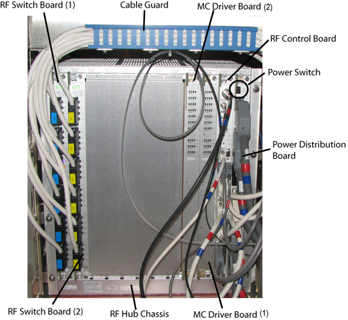
Overview
Note:
When returning RF hub boards, use the original FRU packaging.
This document includes replacement procedures for:
-
RF switch board (RFSB) RF Switch Board
-
Multicoil driver board (MCDB) MC Driver Board
-
RF control board (RFCB) RF Control Board
-
Power distribution board (PDB) Power Distribution Board
-
RF hub chassis RF Hub Chassis
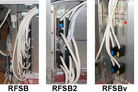
RF Switch Board
About this task
Multiple versions of the RF boards have been used, but the location in the RF hub chassis and the replacement procedures are the same.
Removing RF Switch Board
Procedure
Installing RF Switch Board
Procedure
- Line up the mechanical lever groove with the chassis edge, and
lower the levers to insert the board.
Figure 3. Groove on RF Board Lever 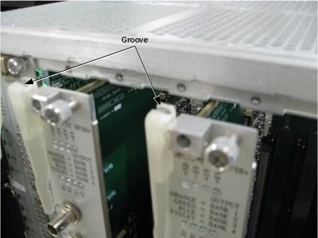 Note:
Note:Make sure the board is fully seated in the RF chassis.
MC Driver Board
Removing MC Driver Board
Procedure
Installing MC Driver Board
Procedure
RF Control Board
Removing RF Control Board
Procedure
Installing RF Control Board
Procedure
Power Distribution Board
Removing Power Distribution Board (PDB or ePDB)
Procedure
Installing PDB
Procedure
RF Hub Chassis
Removing RF Hub Chassis
Procedure
- Remove the three screws directly on top of the vent intake.
Figure 4. Vent Intake Screw Locations 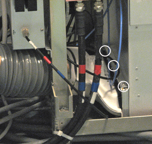
- Remove the seven bolts securing the RF chassis to the rear pedestal.
Figure 5. RF Chassis - Bolt Locations 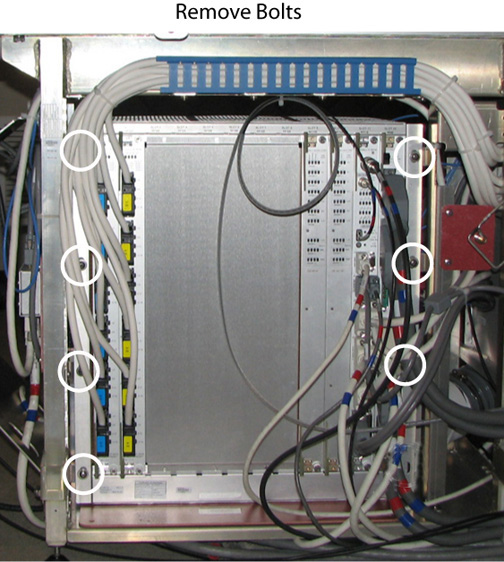
Installing RF Hub Chassis
Procedure
Finalization
Procedure
- Turn on the power switch on the PDB.
- Replace the side covers on the rear pedestal.
- Remove LOTO. See the MR Service Safety Manual, PN 5452735.
- Perform a TPS reset.