
- 00000018WIA307C5030GYZ
- id_123737431.4
- Dec 19, 2019 3:32:01 PM
BrainWave Lite Option Installation
Installation Overview
The GE BrainWave Lite option consists of software and hardware that can be used in combination with third party hardware to present fMRI patient stimuli synchronized with MR scanning. This document describes the hardware installation for this option. The hardware consists of the BrainWave cabinet located in the equipment room, the response system including response pads, and connecting cables. Cable runs must be made from the magnet to the penetration panel, from the penetration panel to the BrainWave cabinet, from the systems cabinet to the BrainWave cabinet, and from the BrainWave cabinet to the control room.
Options Installed
This document describes the installation of GEHC MR catalog number M1033BL–BrainWaveHW Lite option.
Shipping List
The BrainWave hardware is shipped as a partially assembled cabinet (BrainWave cabinet) containing 6 cardboard boxes. The contents of the cabinet and the boxes are listed in the tables below.
| Component | Qty | GE P/N |
| [Cedrus] Lumina response controller box | 1 | 2394034-6 |
| [Cedrus] AC power module for Lumina response controller box | 1 | 2394034-7 |
| 5 foot VGA cable | 1 | n/a (part of 19 inch LCD display 5318540) |
| AC power cable for 15 inch LCD display | 1 | n/a (part of 19 inch LCD display 5318540) |
| Stimulus computer (PC) including AC power cord | 1 | 5922000 |
| Power strip | 1 | 2394034-11 |
| FTDI virtual com port | 1 | 5173956–5 |
| Rack mount | 1 | 5173956–6 |
| Component | Qty | EIZO Model | GE P/N |
| 19 inch monitor
| 1 | MX191 | 5318540 |
| Component | Qty | Cedrus P/N | GE P/N |
| Shielded cable (65 ft (30 m)) to be used inside of the magnet
room (penetration sub-panel to OTEC unit)
| 1 | LG404 | Part of 2394034-9 cable kit |
| Component | Qty | Cedrus P/N | GE P/N |
| Shielded cable (65 ft (30 m)) for use outside of the magnet
room (penetration sub-panel to Cedrus Lumina response pad in the Brainwave
cabinet)
| 1 | LG408 | Part of 2394034-9 cable kit |
| Component | Qty | Cedrus P/N | GE P/N |
| R/L response pads/fiber optic cable/OTEC unit assembly to be
used inside the magnet room
| 1 | LG407 | 2394034-5 |
| Component | Qty | GE P/N |
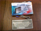
| PC-compatible keyboard to be used with Stimulus PC in the Brainwave
cabinet
| 1 | 2394034-16 |
| Component | Qty | GE P/N |
| Bulkhead threaded clips | 2 | 46-265067P1 |
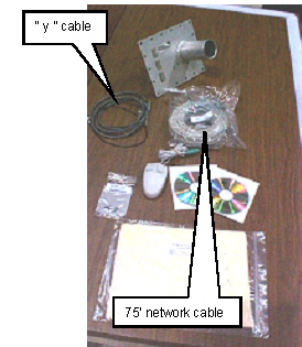
| Y-trigger cable | 1 | 2293552 |
| Penetration sub-panel assembly | 1 | 2394034-10 |
| Two-Button USB Scroll Mouse | 1 | 5763460 |
| Network cable (75 ft) | 1 | 2394034-18 |
| Software key (MOD) | 1 | 5110736 |
| Software installation manual | 1 | 5114982 |
| Software disc | 1 | 5173956–3 |
| Headphones (not shown)
| 1 | 2394034–12 |
Required Tools
-
#2 flat head screwdriver
-
#2 Phillips screwdriver
-
Utility knife
Summary of Tasks
-
Cabinet installation:
-
Install BrainWave Lite cabinet
-
Install LCD monitor
-
Install keyboard and mouse
-
Plug power cords into AC power strip
-
-
Ramp port installation
-
Installation of additional BrainWave Lite cables
-
Power up procedure and hardware system checks
BrainWave Lite Hardware Installation
Interconnect Diagrams
Cabinet Installation
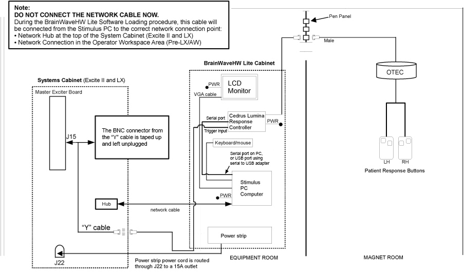
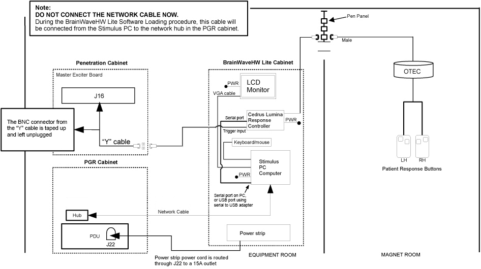
The cabinet must be installed in the equipment room, close to the systems cabinet. The BrainWave Lite option’s power and trigger comes from the systems cabinet for HD-based systems, or from the pen cabinet for DV-based systems.
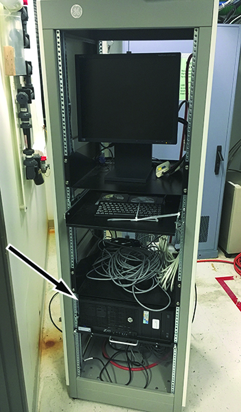
Install BrainWave Lite Cabinet
-
Locate the BrainWave Lite cabinet. Standard lengths of power strip cord (15 ft) and sub-D cable (60 ft) from BrainWave Lite Cabinet to the systems cabinet (for HD-based systems) or the pen cabinet (for DV-based systems) should be considered, as well as customer preference.
-
Level the BrainWave Lite cabinet.
-
Open and verify the contents of boxes 1 through 6.
Install LCD Monitor
-
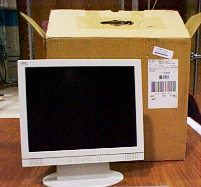
Unpack the LCD monitor (5318540) from box 1.
-
Find the monitor brackets installed in the BrainWave Lite cabinet. Loosen 1 screw in the left monitor bracket. Remove the other 3 screws. Rotate this bracket away from the center of the cabinet.
Figure 4. Monitor Brackets (Cabinet Front View) 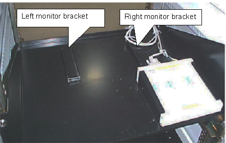
-
Loosen the screws in the right monitor bracket, and slide the monitor base under the right monitor bracket.
-
Rotate the left monitor bracket over the base of the monitor. Reinstall the 3 screws. Tighten all screws on the left and right monitor brackets.
Figure 5. Monitor Brackets with Monitor Installed (Cabinet Rear View) 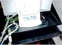
-
Install the DC power cable and the VGA cable to the monitor. These cables are loosely tie-wrapped to the monitor shelf. The other end of this VGA cable may be connected to the rear of the computer now for installation testing, but is usually connected to third party video equipment after the third party equipment is added to the cabinet.
Figure 6. Monitor DC Power Cable and VGA Cable 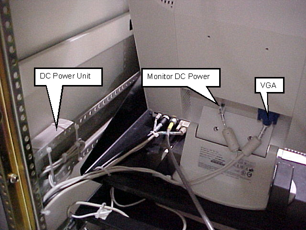
Install Keyboard and Mouse
-
Remove tape at the front of the BrainWave cabinet restraining the slide-out shelf.
-
Unpack the keyboard and mouse from box 6 and place on slide-out shelf.
Figure 7. Keyboard and Mouse on Slide-out Shelf 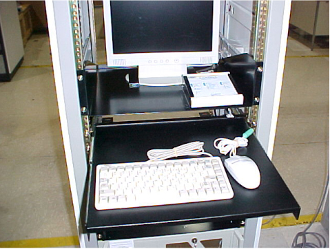
-
Route the keyboard and mouse cables straight back and down to the computer.
-
Plug the keyboard and mouse connectors into PC.
-
Route excess cable down the left side of the cabinet. Loosely tie-wrap the cables away from the shelf slides to prevent the cables from being damaged. Ensure that there is enough slack in the cables to allow the shelf to slide out all the way.
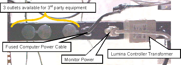
Plug Power Cords into AC Power Strip
Make sure the AC plugs for the Stimulus PC and the monitor are inserted into the AC power strip at the bottom of the BrainWave Lite cabinet. The transformer/plug for the Cedrus Lumina (response system) controller is already tie-wrapped to the AC power strip.
Ramp Port (Waveguide) Installation
For MR750/MR450 systems, the ramp port is called the waveguide.
The original ramp port sub-panel must be removed and replaced with the custom ramp port to allow cabling into the magnet room.
| DANGER | |
|---|---|
| DANGER | |
|---|---|
-
For MR750/MR450 systems, perform LOTO on the PGR and penetration cabinets. See the MR Service Safety Manual, PN 5452735.
-
For earlier systems, perform LOTO on the main PDU breaker. See the MR Service Safety Manual, PN 5452735.
-
For all systems, perform LOTO on the Heat Exchanger Cabinet (HEC) to remove power from the cyrocooler compressor, which is necessary to complete this procedure. See the MR Service Safety Manual, PN 5452735.
-
Unpack the contents of box 6. Place all cables aside, and take the custom ramp port panel.
-
Install the custom ramp port panel (2394034-10) in place of the standard panel.
Figure 9. Sub-Panel 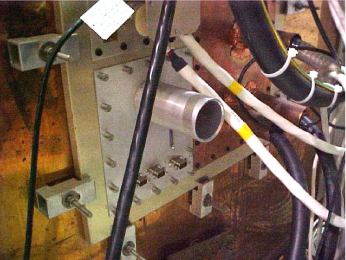 Note:
Note:If the ramp port panel has pre-existing (custom) modifications, they must be reapplied to the sub-panel before installation time.
Installation of Additional BrainWave Lite Cables
Attach Cable from Box 3
-
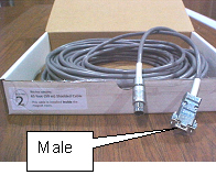
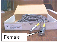
Attach the cable from box 3 (Cedrus LG408) to one of the 9-pin filters at the sub-panel.
Figure 10. Sub-Panel with Cable from Box 3 Installed 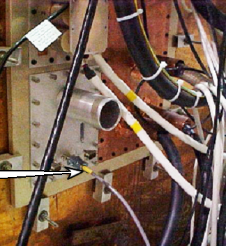
-
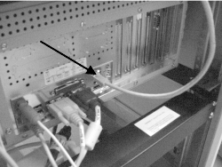
Insert the other end of the cable from box 3 into the back of the Cedrus Lumina control unit.
Figure 11. Cedrus Lumina Controller with Cable Installed (Rear View of BrainWave Cabinet) 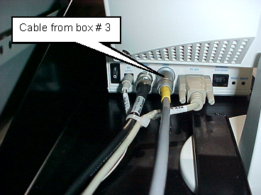
Attach Cable from Box 2
-
Attach the cable from box 2 to the other side of the 9-pin filter inside the magnet room at the sub-panel.
-
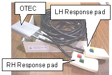
Attach the other side of the cable from box 2 to the OTEC unit inside the magnet room.
Figure 12. OTEC Unit and Response Pads 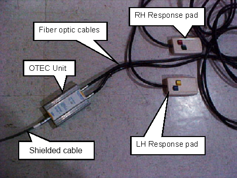
Connections to Excite Systems Cabinet
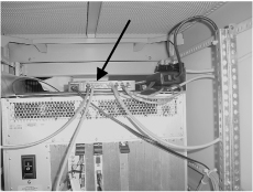
-
Remove the front cover of the systems cabinet. Install cable (2293552) on J15 on the master exciter board (2281038).
Figure 13. J15 Location on Master Exciter Board 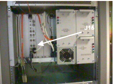
-
Using the screw-lock connectors (46-265067P1), mount the female end of the Y-cable to an open DB-9 access hole from inside the rear panel at the bottom of the systems cabinet.
Connections to MR750/MR450/MR750w/MR450w System
-
Open the pen cabinet. Install cable (2293552) on J16 on the exciter. This cable may enter from the top of the pen cabinet.
Figure 14. J16 Location on Master Exciter Board 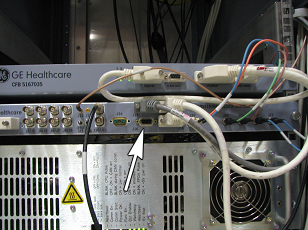
-
Connect the power cable from the top of the PGR cabinet.
Figure 15. Power Cable from BrainWave Cabinet (MR750/MR450) 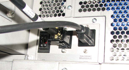
Connections to LX-Based Systems Cabinet
-
Open the rear of the systems cabinet and check for an existing cable on J31 on the Tyme II board.
Figure 16. Tyme and TNF connections 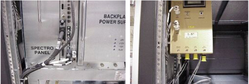
-
If the cable does not exist, connect the Y-cable (2293552) to J31 and do not use the BNC end of the Y-cable (cover the end of the BNC cable with electrical tape). If the cable exists, remove the cable and connect the Y-cable to J31 of Tyme II and J1 to TNS.
-
Using the screw-lock connectors (46-265067P1), mount the female end of the Y-cable to an open DB-9 access hole from the inside of the rear panel at the bottom of the systems cabinet.
Connect Cables to Systems Cabinet
-
Find the long DB-9 cable and the long 3-prong power strip cable located at the bottom of the BrainWave Lite cabinet. Unroll and route these two cables to the systems cabinet, or to the pen cabinet for MR750/MR450.
Figure 17. Cables at Bottom of BrainWave Lite Cabinet 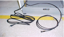
-
Remove the base access panel at the rear of the systems cabinet. Route the cabinet power strip cable through the J22 panel cutout. Plug the power cord into an open 15A outlet. If J22 is full, use other methods to attach the power cable to the systems cabinet.
Figure 18. Systems Cabinet Rear Access Panel (Systems Earlier than MR750/MR450) 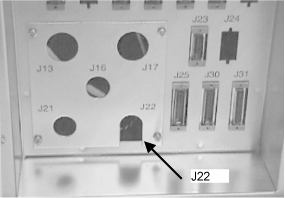
-
Reinstall the access panel to the systems cabinet I/F.
Note:Other uses of the 15A outlets are non-standard and should be evaluated for overall demand. The BrainWave option requires approximately 10A (steady state - assume 15A power-up demand). If there are other pre-existing users of 15A power, and all the 20A outlets are unused, the BrainWave option may be plugged into an open 20A outlet instead.
-
Insert the other cable that was routed to the systems cabinet into the DB-9 access hole in the rear panel of the systems cabinet. This is the same access hole which was used for the female end of the Y cable.
Connecting Ethernet Cable to Excite II System
Connecting Ethernet Cable to LX System
-
Connect one end of Ethernet cable to the Ethernet hub that is inside the duplex.
Figure 21. Duplex Network Connection 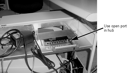
-
Route the other end of the Ethernet cable to the Stimulus PC. See Figure 20. Do not connect the cable at this time. The cable will be connected after the software load.
Connecting Ethernet Cable to MR750/MR450/MR750w/MR450w System
-
Route the Ethernet cable to the MR750/MR450 power cabinet.
-
Connect the Ethernet cable to any open port on the Ethernet hub.
Figure 22. Ethernet Hub 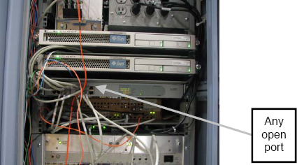
-
Route the other end of the Ethernet cable to the Stimulus PC. See Figure 20. Do not connect the cable at this time. The cable will be connected after the software load.
Power Up Procedure and Hardware System Checks
Start/Stop BrainWave Paradigm Executable Engine (PXE)
-
To temporarily go to the Windows desktop, press Esc. The PXE automatically returns to Idle state after a time out.
-
To exit PXE and go to the Windows desktop, press [Shift-Esc].
-
To start PXE, click the Launch BrainWave PXE desktop icon. The Idle screen displays on the monitor.
Response Pad Check
-
Press the response pad buttons in the magnet room, and have an independent observer at the BrainWave cabinet confirm that the R/G/B/Y LEDs on the response interface box respond accordingly.
Figure 23. Response Pad LEDs 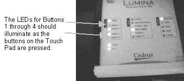
If the LEDs do not respond correctly:
-
Verify continuity between the response pads and the controller:
-
Check that power is reaching the response interface box from the cabinet power strip.
-
Check that the response fiber optic cable is properly connected at the response interface box and the response pad assembly, as well as at the mating connection.
-
-
If the LEDs do not light, check the cabling between the response pads in the magnet room and the controller in the Brainwave cabinet.
-
-
Check the communications between the Stimulus PC, the controller box, and the response pads in the magnet room. The method for checking communications depends on the version of the Stimulus PC.
Older versions of the Stimulus PC have a program called comtest in the C:\Program Files\Sensor Systems\NeuroActivator 1.050W\ folder. Newer versions do not have this program.
For older versions of the Stimulus PC (part 2303343–2):
-
On the Stimulus PC, start the comtest program by opening Windows Explorer then selecting: C:\Program Files\Sensor Systems\NeuroActivator 1.050W\comtest.exe. A window appears.
-
Press the four response pad buttons in the magnet room.
-
The following numeric values should appear:
Blue Number 49 Yellow Number 50 Green Number 51 Red Number 52 -
This verifies communication from the response pads in the magnet room, to the controller box, and then to the Stimulus PC. If there is no response on the PC, check the cabling between the controller box and the PC.
For newer versions of the Stimulus PC (part 5110946):
-
Click the Start on the Windows desktop.
-
Click Hyperterminal.
-
In the Hyperterminal window, select File > Open > cedrus_test.
-
Press the response pad buttons in the magnet room.
-
The following numeric values should appear in the Hyperterminal window:
Blue 1 Yellow 2 Green 3 Red 4 -
This verifies communication from the response pads in the magnet room, to the controller box, and then to the Stimulus PC. If there is no response on the PC, check the cabling between the controller box and the PC.
For the latest PC (HP Z420):
-
Click on Brainwave PXE COMM Test folder on the PC monitor.
-
Scroll down and select the commtest option.
-
Press the response pad buttons in the magnet room.
-
The following numeric values should appear.
Blue Number 49 Yellow Number 50 Green Number 51 Red Number 52 -
This verifies communication from the response pads in the magnet room, to the controller box, and then to the Stimulus PC. If there is no response on the PC, check the cabling between the controller box and the PC.
-
Systems Cabinet Trigger Check
The trigger signal from the exciter is an “active low” signal. The trigger LED on the response pad should be off when the cable is properly connected from the exciter to the response pad. Disconnecting the cable at the response pad should cause the trigger LED to come on. This is a quick method to determine proper continuity between the exciter and the response pad.
-
On the Stimulus PC, start the program for observing results from the check:
-
For older versions of the Stimulus PC: On the Stimulus PC, start the comtest program by opening Windows Explorer, and then selecting: C:\Program Files\Sensor Systems\NeuroActivator 1.050W\comtest.exe. A window appears.
-
For newer versions of the Stimulus PC:
-
On the Windows desktop, select Start > Hyperterminal.
-
In the Hyperterminal window, click File > Open > cedrus_test.
-
-
-
Set up an fMRI scan for the system you are testing. For HD-based systems, see fMRI Scan for HD-Based Systems. For DV-based systems, see fMRI Scan for DV-Based Systems.
Note:To stop the NeuroActivator and keep the screen from constantly displaying the 4 color boxes, right-click the NeuroActivator icon on the Start bar and select Exit. To restart NeuroActivator, click Start > Programs > NeuroActivator > NeuroActivator – Clinical.
The signals are sent through pins 4 and 9 of the DB-9 connector.
fMRI Scan for HD-Based Systems
-
Set up for an fMRI scan using the following parameters:
Patient Position Supine Patient Entry Head first Coil Standard Head coil Plane Axial plane Mode 2D Pulse Sequence Gradient Echo EPI -
Select fMRI imaging option.
-
Click on the fMRI screen in the middle of the monitor and enter the parameters noted below. Click Accept when done.
Figure 24. fMRI Screen 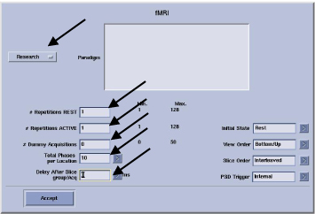
-
Enter the parameters shown below.
Figure 25. fMRI Screen 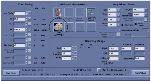
-
Auto prescan and scan.
-
After the scan is complete, check the output from the com test. You should see:
(For older versions of the Stimulus PC) A new pulse received number is 53
(For newer versions of the Stimulus PC) A new pulse received number is 5
This verifies communication between the systems cabinet and the Stimulus PC.
The outputs from the response pads and the system trigger from the systems cabinet are routed through the response system electronics and then to the serial port of the Stimulus PC.
-
If the BrainWave hardware does not receive the trigger from the systems cabinet, the paradigms will not go past the ready state.
-
The response electronics may get “hung up”. If you suspect this is the case, try cycling the power.
-
If response or trigger signals are not present, trace the signals using the interconnect diagram (see Interconnect Diagrams) back through the response electronics.
-
fMRI Scan for DV-Based Systems
-
Click the New Patient icon.
-
Enter geservice for the Patient ID.
-
Enter a patient weight of 222 pounds.
-
Select the protocol:
-
Click Show All Protocols.
-
Select the GE protocol library.
-
Select Head.
-
select GEM: fMRI.
-
Select fMRI Right Hand Movement.
-
-
Click Accept, and then select Start Exam.
-
From the exam page, double-click fMRI Right Hand Movement.
-
Select the coil that is being used. You can use the body coil.
-
Fill in zero for both the start and end location.
-
Click Save Rx, and then click Scan.
-
Observe the Stimulus PC. You should see:
(For older versions of the Stimulus PC) A new pulse received number is 53
(For newer versions of the Stimulus PC) A new pulse received number is 5
This verifies the communication between the systems cabinet and the Stimulus PC.
The outputs from the response pads and the system trigger from the systems cabinet are routed through the response system electronics and then to the serial port of the Stimulus PC.
Field Replaceable Units (FRUs)
| Part Number | Description |
| Not a FRU. Open a CSO. | PC and platform software assembly |
| 5110767 | BrainWave application software CD-ROM |
| 5110968 | Patch CD for BrainWave Stimulus PC |
| 5318540 | 19 inch LCD display with 5 ft VGA cable needed for computer connection (Amtran) |
| 2394034-5 | [Cedrus] Response pad assembly, left and right hand units with two buttons for each hand, includes fiber optic cable (20 ft) and optical converter box |
| 2394034-6 | [Cedrus] Lumina response controller box. |
| 2394034-7 | [Cedrus] AC power module for Lumina response controller box |
| 2394034-9 | (FRU usage only) Kit containing all cables [Cedrus-4, -5, -6, -7, 2xxxxxx-6, 46-265057P1 (qty 2)] |
| 2394034-10 | Penetration sub-panel assembly |
| 2394034-16 | PC compatible keyboard (narrow) |
| 5763460 | Two-Button USB Scroll Mouse |
| 5110736 | Excite II scanner license key MOD for the BrainWave hardware option |
Upgrading to Excite Configuration from Pre-Excite
Hardware Configuration
When upgrading from a pre-Excite to an Excite configuration, the following changes are needed:
-
Remove the data cable from the systems cabinet Tyme board, J31.
-
Install the data cable to J15 on the master exciter board (PN 2281038).
Figure 26. J15 Location on Master Exciter Board -
Install the provided network cable between the Stimulus PC network output and the systems cabinet hub located at the top of the systems cabinet. Do not connect the cable at this time. The cable will be connected after the software load.
Figure 27. Systems Cabinet Network Connection
Software Configuration
Configuration Procedure for Advanced Users
-
Exit NeuroActivator.
-
Click Start > Settings > Control Panel > Network.
-
Click the Protocols tab.
-
Select the TCP/IP protocol.
-
Click Properties.
-
In the IP Address field, enter the GESTIMPC IP address.
-
In the Subnet Mask field, enter 255.255.252.0.
-
Leave the Default Gateway field blank.
-
Click OK.
-
Click OK.
Configuration Procedure for New Users
-
Move the mouse to dismiss the flashing square. Right-click the NeuroActivator icon (image of the brain in the lower right hand corner of the task bar), and then click Exit.
-
Launch the Windows Network configuration utility. Click Start > Settings > Control Panel. Double-click the Network icon.
-
Click the Protocols tab.
-
Select the TCP/IP protocol.
-
Click the Properties button.
-
Start a C shell.
-
In the C shell window, enter the following command:
more /etc/hosts
-
In the IP Address field of the Protocols tab, enter the gestimpc IP address from the C shell.
-
In the Subnet Mask field, enter 255.255.252.0.
-
Leave the Default Gateway field blank.
-
Click OK.
-
Click OK.
-
Close the C shell window.