there is pressurized liquid inside the HEC cabinet when
energized. See the MR Service Safety Manual, PN 5452735.
wear nitrile gloves when handling coolant.
Coolant Draining
About this task
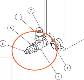
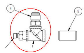
The HEC facility tee with QD (quick disconnect) is located in
the rear of the lower portion of the heat exchange cabinet (HEC).
This assembly provides facility coolant to the heat exchangers for
both the power electronics (PE) and gradient coil (GC) loops.
Figure 1. HEC Facility Tee with QD
Procedure
Perform LOTO on the HEC. See the MR Service Safety Manual, PN 5452735.
Drain the facility water from the cabinet according to Coolant Draining.
Drain the appropriate coolant reservoir according to Coolant Draining:
If replacing the PE side facility tee with QD, drain the PE
tank only.
If replacing the GC side facility tee with QD, drain both tanks.
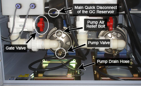
Drain the respective pump through the small clear pump drain
hose, by placing it into a bucket and loosening the pump air relief
bolt.
Figure 2. Pump Drain Hose Location
Facility Tee Removal
Procedure
Notice
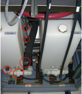
Before you disconnect the hoses, take notes on the connections or label the hoses and cables, so that you can properly reattach the hoses.
Disconnect all hoses and sensor cables from the appropriate
coolant reservoir.
Figure 3. Hoses and Sensor Cables
Remove the pump shield(s) from the underside of the coolant
reservoir (just above the pumps) and maneuver out the front of the
cabinet in order to access screws for reservoir removal. Depending
on the cabinet revision, the pump shield may not be present.
Remove appropriate coolant reservoir(s) from the cabinet by
removing the screws from the underside.
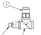
Disconnect the facility hose from the top of the facility tee.
Figure 4. Removing Facility Hose from Facility Tee
Unthread the assembly from the pipe nipple in the heat exchanger.
Figure 5. Cryo Supply Header Removal
Note:
An additional pipe nipple is shipped with the FRU. It
can be used as needed to replace the pipe nipple in the HEC.
Facility Tee Installation
Procedure
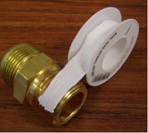
Apply Teflon tape to the pipe nipple still attached to the heat
exchanger before installing the replacement facility tee assembly.
When applying new Teflon tape, start one thread in from the
end of the male thread, to prevent tape from entering the fluid passage.
Figure 6. Application of Teflon Tape
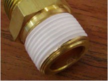
Because Teflon tape is not adhesive-backed, hold the end of
the tape with a finger until one full wrap is completed. Wind the
tape in a clockwise direction (as viewed from the end of the fitting).
This ensures that the installation of the mating components results
in wrapping the tape in the same direction, rather than unwinding
it.
Figure 7. Correct Application of Teflon Tape
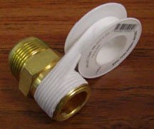
After the first wrap, continue wrapping in a clockwise direction
with moderate tension applied to the tape roll. Overlap the prior
layer by a half width of the tape. This ensures that two layers of
tape cover all threads of the fitting.
Figure 8. Teflon Tape Overlap
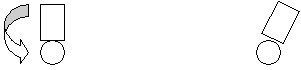
Threading the new assembly onto the pipe nipple assembly takes
approximately 3½ to 4 turns. Take this into consideration when
attaching. You may need to offset the initial position to ensure vertical
alignment.
Figure 9. Initial Offset Viewed from Cabinet Front
Reattach the facility hose to the top of the facility tee.
Reinstall the coolant reservoirs and pump shield in the cabinet.
Reconnect all hoses and sensors previously removed.

 Note:
Note: