- Topic ID: id_17423204
- Version: 9.0
- Date: Jan 23, 2022 10:51:12 PM
X-Ray Tube Replacement
Prerequisites
Overview
This document provides the necessary steps to replace and configure the x-ray tube for imaging. There are two types of tube:
-
Performix 40 (BB) Tube
-
Performix 40 Plus (LB) Tube
1 Old Tube Removal
Procedure
 danger
- danger
- Remove and set aside gantry side, top and front covers.
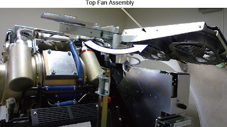
- Slide out the gantry rear cover, and rotate the top fan assembly outward.
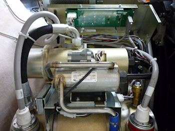
Figure 1. Top Fan Assembly
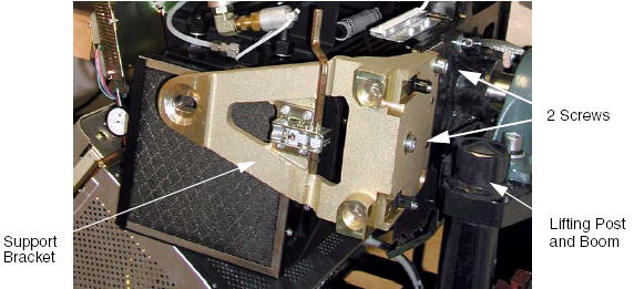
- Remove the M10 screws holding support bracket for the right front gantry cover and set the assembly aside. (For CT System Only) It may be necessary to tilt the gantry back to remove the third bolt if present which is not normally installed on some systems.
(For PET Systems Only with the BrightSpeed Gantry) There may or may not be a lower screw present. If the lower screw is present it must be permanently loosened and left loose using the short stubby 8 mm hex wrench provided with FMI 13693. The wrench is located in the Service Cabinet on site. If necessary this wrench (P/N 5367896) can also be ordered and should be left on site.
Figure 2. Right Front Gantry Cover Support Bracket
- Stop the rotor of X-ray tube in case of Liquid Bearing Tube before HVDC off. Refer to Liquid Bearing Tube Rotor stop procedure for details.
- notice
- Turn off the AXIAL DRIVE ENABLE, HVDC ENABLE, and 120VAC switches.
- Turn off facility power to PDU and lockout/tagout according to lockout/tagout procedure.
- Rotate the Gantry until the x-ray tube reaches the 3 o’clock position.note: It may be easier to loosen the M12 tube mounting bolts with the tube at about the 2 o’clock position before locking the tube at the 3 o’clock position. Simply loosen the tube mounting bolts one half (1/2) turn. Do not remove the bolts yet.
Figure 3. Tube Angle to Loosen and Torque M12 Screws
- warning
- notice
- Engage gantry rotational lock, and check that the gantry is securely locked by attempting to rotate the gantry by hand.
- warning
- Insert the lifting post, boom and chain hoist. Reference Figure 2.
- Disconnect the Smart I.D. system cable, from the Smart I.D.
- Disconnect the 4 pin mate-n-lock pump and fan power system cable.
- Disconnect the thermal sensor cable.
- Remove the anode and the cathode cable:
-
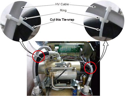
Carefully cut tie-wraps securing HV cables. Note HV cable routing.
note:If ring is used, keep the ring on HV cable side (see Figure 4).Figure 4. HV Cable Ring
-
Loosen each cable’s locking ring with the spanner wrench.
-
Pull each cable terminal out of its receptacle.
-
Ground the end of the cables to the Gantry frame.
-
Wipe up any oil that drips from the cable terminal.
-
Use paper towels to soak up any oil in the wells.
-
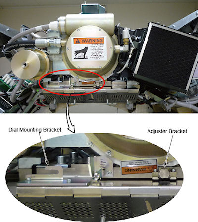
Remove the dial mounting bracket
-
Remove the z-align adjuster bracket
Figure 5. Dial Mounting Bracket and Adjuster Bracket

- caution
note: It may be easier to tape the socket to the extension. This will prevent the socket from being dislodged on the tube radiator assembly -
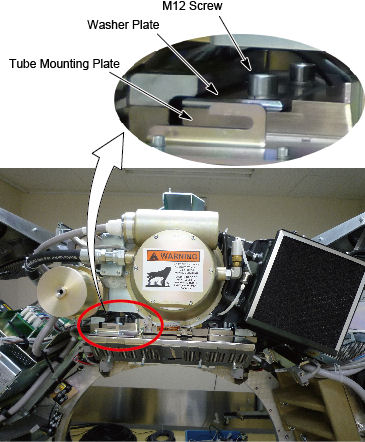
- The x-ray tube is attached to the Collimator with a Tube Mount Bracket Assembly. Remove the mounting plate & x-ray tube from the Collimator by removing the four M12 cap screws and lock washers, and two washer plates, with a hex socket driver. With your hand, reach behind the radiator to the screws from either side of the Xx-ray tube center section while removing the bolts with two 12-inch extensions (24 inch length) on a ratchet. Throw these M12 bolts and washers away, as they should not be reused.
- Remove M12 cap screws.
- Remove the washer plate
- Slide the x-ray tube forward and remove it.
- Throw these M12 bolts and washers away, as they should not be reused.
Figure 6. X-Ray Tube Mounting
- Carefully swing the tube clear of the gantry.
- Inspect the Bowtie Filter (refer to Inspect Collimator Filters). It is possible that the Bowtie Filter is contaminated and the Primary Copper Filter is not contaminated.
- Verify that the Lexan plastic has been removed from the collimator. If it is still there, remove it following the procedures in Lexan Removal .
 |
|
 |
2 New Tube Installation
Procedure
- danger
- danger
- warning
- Allow the tube unit to warm to room temperature before you install it.
- Remove all package from the new tube.
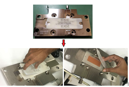
- Remove the plastic protective cover and the thick paper cover from the tube copper filter.
Figure 7. Remove the Plastic protective Cover and Paper Cover
- Re-check facility power and make sure it is off.
- warning
- Use the hoist to lift the new tube unit:
- Position the tube on the gantry: The “crosses” on the mounting plate and on the collimator should fit in perfectly when the tube is aligned properly
- Install the washer plate.note:
-
To ease installation, fasten the top pressure plate to the rotating structure first. Then attach the bottom pressure plate.
-
Use new bolts and washers from tube crate. Make sure to select the proper bolts. There are instructions in the crate, and on the tube itself.
-
- Fasten the lower and upper and pressure plates to the rotating structure with the four M12 (50 mm) bolts, and set pre-load torque to:
- Set final torque to:
- Install the following brackets:
-
Z-Align Adjuster Bracket
-
Dial Mounting Bracket
-
- Connect the Smart ID to the tube smart ID board.
- Connect the tube pump and fan power cable to the 4 pin mate-N-Lock connector.
- Connect the thermal sensor cable.
- Remove the plastic cap plug from each cable receptacle on the tube unit.note: Take care not to lose the rubber quad rings for the High Voltage cables.
- Lightly wet the new rubber quad ring with transformer oil.
- Return the quad ring to its slot at the top of the receptacle retaining ring.
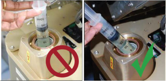
- Pour transformer oil into the receptacle approximately 13 ml (reference only, please adjust the oil amount as necessary).note: DO NOT use the syringe in vertical position, this will result in air bubbles which increase the chances of the high voltage breakdown.
Figure 8. Filling Receptacle
- notice
- Be sure to route the HV cable as shown in Figure 9.
Figure 9. HV Cables Properly Routed and Secured
- Align the cable terminal orienting key with the notch in the receptacle.
- notice
- Slowly insert the cable, to engage the connector pins, and seat the cable in the receptacle.note:
After installing the cable to the receptacle, confirm the transformer oil is spilled over a little from the receptacle as shown in Figure 10.
If the transformer oil is inappropriate amount, adjust the oil amount as necessary.
Figure 10. Appropriate Amount of Transformer Oil
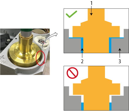
1 HV Cable 2 Transformer Oil 3 Receptacle - notice
- Carefully wipe up all excess oil.
- Tighten the cable locking ring by 1/4 to 1/2 of a full turn after the gap is closed and friction is felt by hand.
- Secure HV Cables using large tie-wraps, as shown in Figure 9.
- Disconnect hoist from tube and boom.
- Remove the post and boom from the gantry, and store them in service cabinet or some other safe place.
- Check for oil leaks:
-
Wrap rags or paper towels around the cable horns, and tape them into place.
-
Manually rotate the tube to the 6 o’clock position.
-
Return the tube to the 3 o’clock position
-
Remove the toweling and wipe up all excess oil.
-
Wipe off the cable horns, locking rings and strain reliefs with an alcohol-dampened rag.
-
Repeat with a dry rag.
-
Wrap the cable strain reliefs and locking rings with a single layer of absorbent paper tissue. You can use two inch wide strips cut from a paper napkin.
-
Wrap the bottom edge of the paper around the top end of the cable horn, and tape it in place.
-
Extend the top edge of the paper over the top of the locking ring, and tape it to the plastic cable strain relief.
-
Remove paper after leak check.
-
- If oils leaks are found, tighten the locking ring slowly until there is no leakage, paying attention to not over tighten.
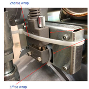
- Attach tie-wrap to fix the SmarID connector as shown in Figure 11 (second tie-wrap).
Figure 11. Tie-wrap Attachment
- Install the right gantry front cover bracket. Reference Figure 2.note: For PET systems only reinstall the top M10 screw. If the lower screw is present on a PET system do not tighten it. leave the lower screw loose.
- Restore system power at the main disconnect panel.
- Turn on gantry 120 VAC, HVDC ENABLE and AXIAL DRIVE ENABLE on the service switch panel. Wait at least 10 minutes to warm up the filament.
- Press [ESTOP RESET] on Service Switch Panel and wait until scan hardware is reset.
|
3 Setup, Checks, Alignments and Calibrations
Procedure
- Checklist
- New mounting bolts and washers are used for mounting the tube; old mounting bolts and washers are discarded.
- Proper torque specifications are followed for all fasteners (see Torque Wrench Information).
- Tie-wraps and cables are in place.
- -
- Tube Install Certification
- Gantry Rotation Safety Check
- Reset TnT (Only select Tube TnT Data)
- Z-Alignment
- Cold ISO Alignment
- Gantry Balance Procedure
- Meter Verification
- HV Tank Feedback Resistor Verification
- Filament Calibration
- HHS Scans
- Hot ISO Alignment
- Turn OFF [HVDC ENABLE], [AXIAL DRIVE ENABLE] and [120VAC] switches on the Service Switch panel.
- Install the gantry front cover, rear cover, top cover, left side cover and scan window.
- Turn ON [HVDC ENABLE], [AXIAL DRIVE ENABLE] and [120VAC] switches on the Service Switch panel.
- Press [ESTOP RESET] on the Service Switch panel, and wait until scan hardware is reset.
- Install the gantry right side cover.
- Collimator Calibration
- Detailed Calibration
- Fast Calibration
4 Finalization
Procedure
- Quality Assurance Test
- New Tube Configure
- Save Generator Runtime Parameters (See Save Restore Generator Runtime Parameters)
- Save System State
- Prepare tube crate for returning old tube. note: Use provided labels to identify old tube as good or defective.note: If tube is being restocked as good, re-band cardboard to crate using strapping instructions provided in crate.