- Topic ID: id_16157521
- Version: 6.0
- Date: Jan 20, 2020 8:36:39 PM
HV Tank Feedback Resistor Verification
Prerequisites
Overview
This procedure verifies the kV accuracy, by actually taking scans with connecting a high voltage bleeder.
Procedure
 caution
- Perform warm-up scans, if the x-ray tube is cold.
- Remove gantry right side cover.
- Stop the rotor of X-ray tube in case of Liquid Bearing Tube before HVDC off. Refer to Liquid Bearing Tube Rotor stop procedure for details.
- Turn off all three service switches on the Service Switch Panel (Axial Drive, HVDC, 120VAC)
- Remove and set aside the top and front gantry covers.
- Rotate the gantry such that the x-ray tube is in the 3 O'clock position.
- Lock the gantry in position, using the rotational lock. Ensure that gantry rotation is locked by attempting to rotate the gantry by hand.
- Free the HV cables.
- Carefully cut ty-raps securing HV cables. Note HV cable routing.
- Loosen the cable's locking rings with a spanner wrench.
- Pull cable terminal sticks out of their receptacles on HV and HEMIT tanks. Oil will leak-cover them quickly!
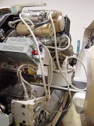
- Install the HV bleeder among the HV tank, HEMIT tank and tube. Use the patient table to place the bleeder. See Figure 1 and Figure 2.note:
X-ray tube Anode guide pin has difference position depending on the type of anode bearing. Connect HV bleeder by disconnecting the HV cable on HEMIT +ST in case of Liquid Bearing Tube (Yellow tag on Anode HV cable).
Figure 1. Bleeder Connection Block Diagram
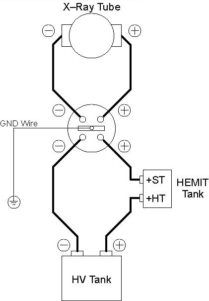
Figure 2. Bleeder Connection
- notice
- Unlock the gantry, and rotate the gantry such that the x-ray tube is in the 12 O'clock position.
- Lock the gantry in position.
- Setup the oscilloscope.
- To minimize noise and obtain a common ground, you should plug the oscilloscope into either the gantry or the console.
- Use 10x, Input resistance 10Meg ohm probe.
- Connect channel one probe to Anode output of bleeder, GND to GND. Connect channel two to Cathode output of bleeder , GND to GND.
- Set horizontal scale = 200 ms, vertical scale = 20V/div( This is for 1kV/volt scale bleeder, apply appropriate scale depending on the bleeder model).
- Trigger channel one, positive slope, DC couple, trigger mode normal.
- Turn ON the 120VAC and HVDC ENABLE on the Service Switch Panel.
- Clear the E-Stop condition by pressing the DRIVES RESET button on the Service Switch Panel.
- Wait about 2 minutes for the gantry display to reset. No flashing lights on the gantry display should indicate this.
- Launch KV & MA (X-RAY).
- Verify the following scan parameters:
-
X-Ray test type = manual
-
Gantry = Disabled
-
Exposure time = 1s
-
No of scans = 1
-
Focal Spot = Large
-
kV = 80kV
-
mA = 40mA
-
- Press RUN and take scan.
- Measure the output :
Using the subtract function on oscilloscope , measure the mean for total kV( channel one - channel two) just inside front edge to just inside back edge of the waveform.
If the scope doesn't have subtract function, measure the mean separately for Anode and Cathode. Then, calculate for total kV.
- Record the console displayed kV value.
- Repeat the measurements for 100, 120, and 140kV scans.
- Verify internal scan timer.
- Adjust trigger level to TTL if necessary.
- Take the following scan.
-
X-Ray test type = manual
-
Gantry = Disabled
-
Exposure time = 1s
-
No of scans = 1
-
Focal Spot = Large
-
kV = 100kV
-
mA = 40mA
-
- Measure the output.
Using cursors on the oscilloscope, measure the scan time (Δt) from just inside the front edge to just inside the back edge of the waveform.
- notice
- Reconnect HV cables from tube to tanks.
 |
 |
|
Finalization
- Scale factor for your kV measurement is 1kV/volt ( this is about 46-154966G1, apply right scale factor depending on bleeder model).
- To pass the kV check, all three of the following conditions must be met.
-
Measured kV reading must be within 3% of selected kV.
-
On-screen reading must be within 3% of selected kV.
-
Measured kV must be within 2% of on-screen reading.
-
- The internal scan timer measurement should be within ±4%.
- Record the results on the HHS data sheet and / or take appropriate service action.