- Topic ID: id_15460699
- Version: 2.0
- Date: Nov 8, 2018 1:39:46 AM
Cold ISO Alignment
Prerequisites
Overview
This document provides the necessary steps to align the X-Ray Tube with the Detector and Collimator in X-axis direction.
1 Data Acquisition
Procedure
- Move table to longitudinal home position.
- Remove scan window.
- Select CALIBRATION from Service Desktop.
- Select ISO ALIGNMENT.
- If Attention window is displayed when tool
is launched, CAREFULLY READ and click ACCEPT.note:
Tube Install Certification service procedure will need to be performed as part of the Finalization section.
note:If CANCEL is clicked, the tool is dismissed.
- Once the ACCEPT button is clicked, another Attention window will be displayed. CAREFULLY READ and click OK.
- Click SCAN to execute air scans.
- Press START on SCIM when it flashes.note:
If one or more tube spits occur, repeat steps 7 and 8.
- Attach a 1/8-inch diameter round metal pin to gantry end of cradle, or to phantom holder.
- Turn on laser alignment lights.
- Move table toward gantry until axial internal alignment lights are aligned with metal pin's mid-point.
- Adjust phantom holder side knob until metal pin is 35mm to right of sagittal internal alignment lights.
- Move table elevation until coronal internal alignment lights are aligned with metal pin.
- Move table up 35mm above scan plane.
- Click SCAN to execute pin scans.
- Press START on SCIM when it flashes.note:
If one or more tube spits occur, repeat steps 15 and 16.
- Click CALCULATE.
- If no adjustments are required, click DISMISS and skip to section 5.
2 Mechanical Alignment
Procedure
- Move table to longitudinal home position.
- Remove right side gantry cover.
- Turn off HVDC ENABLE, AXIAL DRIVE ENABLE and 120 VAC ENABLE switches on Service Switch panel.
- Remove scan window, gantry left side cover, gantry top covers
and gantry front cover.note:
Gantry front-cover control panels and display functionality are required during this procedure.
- Manually rotate gantry until X-Ray tube reaches 2 o'clock position.
- Engage rotational lock.
- Mount dial indicator gauge on Z-Axis mounting bracket, located
on tube assembly front face, with gauge's probe resting perpendicular
to tube casting's front face (Item 1 in Figure 1)
Figure 1. Dial Indicator Mounting and Adjustment Screws Locations
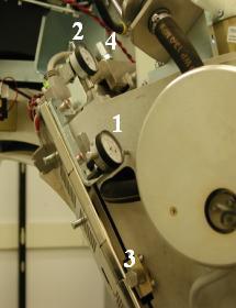
- Mount dial indicator gauge on X-Axis mounting bracket, located on tube assembly left face, with gauge's probe resting perpendicular to tube casting's left face (Item 2 in Figure 1)
- Set both dial indicators to zero.
- Loosen four M12 mounting bolts on tube assembly about 1/4 to 1/2 turns with a 10mm hex bit socket drive and 12 inch extension.
- Turn X-axis adjustment screw (Item 4 in Figure 1), located on tube assembly left side, in direction specified by
ISO Alignment tool, until dial indicator shows ISO-Alignment calculated
value.
EXAMPLE: "-0.06(mm) –0.00230(inches) DOWN"
note:1 mil is equal to 0.001 inches.
note:Turn the adjustment screw clockwise for "Down." Turn the adjustment screw counter-clockwise for "Up."
- If Z-axis dial indicator shows that tube moved left or right, turn Z-axis adjustment screw (Item 3 in Figure 1) to position tube back to its original left-right position.
- Tighten four M12 mounting bolts on tube assembly in a cross
pattern configuration, with a 10mm hex bit socket torque wrench and
12 inch extension, to the following torque values:note:
Ensure that neither dial indicator values change during tightening step.
- Disengage rotational lock.
- Turn on 120 VAC ENABLE, AXIAL DRIVE ENABLE and HVDC ENABLE switches on Service Switch panel.
- Press ESTOP RESET on Service Switch panel and wait until scan hardware is reset.
- Click RESTART from ISO Alignment tool and repeat Section 4.1, Steps 4 – 15 until no adjustments are required.
- Perform Z-Alignment.note:
If adjustments were made during Z-Alignment, repeat Section 4.1 of this procedure. Cold ISO Alignment must always be the last adjustment made.
- Remove dial indicators.
- Verify dial indicator mounting-bracket screws are tight.
3 Finalization
Procedure
- Gantry Balance Procedure
- Hot Iso Alignment
- Turn off HVDC ENABLE, AXIAL DRIVE ENABLE and 120 VAC ENABLE switches on Service Switch panel.
- Install gantry front cover, gantry top covers, gantry left side cover and scan window.
- Turn on 120 VAC ENABLE, AXIAL DRIVE ENABLE and HVDC ENABLE switches on Service Switch panel.
- Press ESTOP RESET on Service Switch panel and wait until scan hardware is reset.
- Install right side gantry cover.
-
Tube Install Certification
note:
Make sure the Tube Identity is set CORRECTLY.
- Collimator Calibration
- Detailed Calibration
- Fast Calibration
- System Scanning Test
- Quality Assurance Test
- Save System State