- Topic ID: id_15460298
- Version: 2.0
- Date: Nov 8, 2018 1:36:54 AM
Cold ISO Alignment
Prerequisites
Overview
This document provides the necessary steps to align the X-Ray Tube with the Detector and Collimator in X-axis direction.
1 Data Acquisition
Procedure
- Move table to longitudinal home position.
- Remove scan window.
- Select CALIBRATION from Service Desktop.
- Select ISO ALIGNMENT.
- If Attention window is displayed when tool
is launched, CAREFULLY READ and click ACCEPT.note:
Tube Install Certification service procedure will need to be performed as part of the Finalization section.
note:If CANCEL is clicked, the tool is dismissed.
- Once the ACCEPT button is clicked, another Attention window will be displayed. CAREFULLY READ and click OK.
- Click SCAN to execute air scans.
- Press START on SCIM when it flashes.note:
If one or more tube spits occur, repeat steps 7 and 8.
- Attach a 1/8-inch diameter round metal pin to gantry end of cradle, or to phantom holder.
- Turn on laser alignment lights.
- Move table toward gantry until axial internal alignment lights are aligned with metal pin's mid-point.
- Adjust phantom holder side knob until metal pin is 35mm to right of sagittal internal alignment lights.
- Move table elevation until coronal internal alignment lights are aligned with metal pin.
- Move table up 35mm above scan plane.
- Click SCAN to execute pin scans.
- Press START on SCIM when it flashes.note:
If one or more tube spits occur, repeat steps 15 and 16.
- Click CALCULATE.
- If no adjustments are required, click DISMISS and skip to section 5.
2 Mechanical Alignment
Procedure
- Move table to longitudinal home position.
- Remove right side gantry cover.
- Turn off HVDC ENABLE, AXIAL DRIVE ENABLE and 120 VAC ENABLE switches on Service Switch panel.
- Remove scan window, gantry left side cover, gantry top covers
and gantry front cover.note:
Gantry front-cover control panels and display functionality are required during this procedure.
- Manually rotate gantry until X-Ray tube reaches 2 o'clock position.
- Engage rotational lock.
- Mount dial indicator gauge on Z-Axis mounting bracket, located
on tube assembly front face, with gauge's probe resting perpendicular
to tube casting's front face (Item 1 in Figure 1 and Figure 2)
Figure 1. Dial Indicator Mounting and Adjustment Screws Locations (Performix Pro VCT 100 / Performix HD, Ball Bearing)
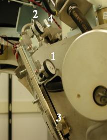
Figure 2. Dial Indicator Mounting and Adjustment Screws Locations (Performix VCT Plus / Performix HD Plus, Liquid Bearing)
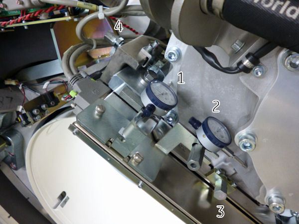
- Mount dial indicator gauge on X-Axis mounting bracket, located on tube assembly left face, with gauge's probe resting perpendicular to tube casting's left face (Item 2 in Figure 1 and Figure 2)
- Set both dial indicators to zero.
- Loosen four M12 mounting bolts on tube assembly about 1/4 to
1/2 turns with a 10mm hex bit socket drive and 12 inch extension.
In case of Performix VCT Plus or Performix HD Plus tube (Liquid Bearing), Low profile 19mm socket or a Crowfoot wrench extension may be used in order to access front M12 bolts. Also be careful not to hit dial gage when loosening the bolt.
Figure 3. Crow Foot Wrench
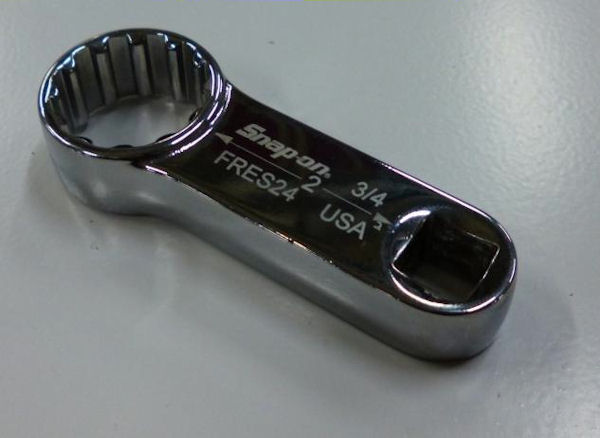
Figure 4. Crow Foot Wrench with Torque Wrench
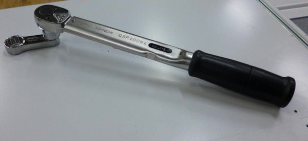
Figure 5. Hitting Dial Gage
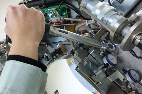
Figure 6. Low profile 19mm socket
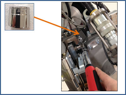
- Turn X-axis adjustment screw (Item 4 in Figure 1 and Figure 2), located
on tube assembly left side, in direction specified by ISO Alignment
tool, until dial indicator shows ISO-Alignment calculated value.
EXAMPLE: "-0.06(mm) –0.00230(inches) DOWN"
note:1 mil is equal to 0.001 inches.
note:Turn the adjustment screw clockwise for "Down." Turn the adjustment screw counter-clockwise for "Up."
- If Z-axis dial indicator shows that tube moved left or right, turn Z-axis adjustment screw (Item 3 in Figure 1 and Figure 2) to position tube back to its original left-right position.
- Tighten four M12 mounting bolts on tube assembly in a cross
pattern configuration, with a 10mm hex bit socket torque wrench and
12 inch extension, to the following torque values:
In case of Performix VCT Plus or Performix HD Plus tube (Liquid Bearing), crow foot wrench shall be used in order to access front M12 bolt.
note:Ensure that neither dial indicator values change during tightening step.
- Disengage rotational lock.
- Turn on 120 VAC ENABLE, AXIAL DRIVE ENABLE and HVDC ENABLE switches on Service Switch panel.
- Press ESTOP RESET on Service Switch panel and wait until scan hardware is reset.
- Click RESTART from ISO Alignment tool and repeat Section 4.1, Steps 4 – 15 until no adjustments are required.
- Perform Z-Alignment.note:
If adjustments were made during Z-Alignment, repeat Section 4.1 of this procedure. Cold ISO Alignment must always be the last adjustment made.
- Remove dial indicators.
- Verify dial indicator mounting-bracket screws are tight.
3 Finalization
If this procedure has been done a part of Tube Replacement procedure, do not execute this Finalization steps and return to Tube replacement procedure for remaining steps.
Procedure
- Gantry Balance Procedure
- Turn off HVDC ENABLE, AXIAL DRIVE ENABLE and 120 VAC ENABLE switches on Service Switch panel.
- Install gantry front cover, gantry top covers, gantry left side cover and scan window.
- Turn on 120 VAC ENABLE, AXIAL DRIVE ENABLE and HVDC ENABLE switches on Service Switch panel.
- Press ESTOP RESET on Service Switch panel and wait until scan hardware is reset.
- Install right side gantry cover.
- Hot Iso Alignment
-
Tube Install Certification
note:
Make sure the Tube Identity is set CORRECTLY.
- Collimator Calibration
- Detailed Calibration
- Fast Calibration
- System Scanning Test
- Quality Assurance Test
- Save System State