- Topic ID: id_15460141
- Version: 2.0
- Date: Nov 8, 2018 1:36:38 AM
SmartStep Option Installation
The SmartStep hardware is shipped ready for immediate installation. The following installation procedure describes how to install the hardware on the gantry through general layout of cabling and connections. Refer to the SmartStep Owners Manual for operation.
1 Preparation
Prerequisites
-
Must have all components in B7877ZS Smart Step Collector - including software and hardware.
-
Must have hardware kit.
|

Cover Removal
-
Remove the gantry side covers. Refer to the System Service Methods for procedure on gantry cover removal.
-
Turn OFF gantry service switches, Axial Drive, HVDC, and 120 VAC.
-
Remove both left and right side gantry base side covers, and then remove the gantry base rear covers. Refer to the System Service Methods for procedures on gantry cover removal.

- notice
2 Interconnects and Functional Drawings
-
For CT systems equipped with Inter Process Communication Panel (IPC) see:
-
For PET systems equipped with Inter Process Communication Panel (IPC) see:
-
For CT and PET systems equipped with Gating Options Board (GOB) see:
-
For CT and PET systems using a 16 or 8 or 4 Slice Gantry see:
Interconnects for SmartStep on CT and PET systems with 16/8/4 Slice Gantry
3 Overview and Finalization
3.1 Overview
During needle biopsies, the Radiologist or Physician controls radiation with the foot switch, and uses the hand-held controller (HHC) to view images on the in-room monitor. The HHC also provides alignment light, move-to-scan, and cradle micro positioning controls. The Radiologist or Physician also has the option to release the HHC control of the cradle, and use the cradle handle to manually position the patient in the scan field of view.
3.2 Finalization
3.2.1 Install SmartStep Cradle Handle and HHC holder
Figure 1. SmartStep Cradle Handle and Holder Install
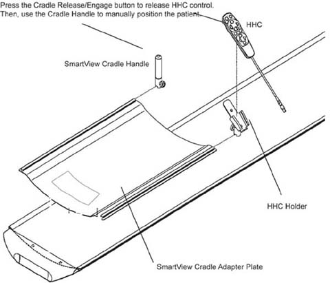
-
Remove the patient pad from the cradle and set aside.
-
Remove and discard the four plastic covers shipped on the cradle adaptor plate.
-
Remove and discard the front four plastic caps that cover the cradle screws.
-
Orient the cradle handle adaptor plate, and lay it on the cradle top so the four “feet” on the bottom of the adaptor plate rest into the front four cradle screw holes. This prevents slippage during the manual positioning.
-
Return the patient pad to the cradle.
-
Slide the HHC holder and cradle handle onto the cradle adpater plate. Orient them such that the knurled knobs face away from the cradle.
-
Secure the holder and handle into place by tightening the knurled knobs.
note:The cradle handle may have some small lateral movement. This is normal.
3.2.2 Testing and Cover Re-Installation
-
Clear all obstructions to gantry motion and turn ON all three switches Axial Drive, HVDC, and 120 VAC on the service switch panel.
-
Complete System Scanning Test. Refer to the system’s Service Methods for this procedure.
-
Check SmartStep Operation. Refer to SmartStep Operator’s Manual.
-
Perform Patient Touch Test.
-
Before re-installing the base covers of the gantry turn OFF all three switches Axial Drive, HVDC, and 120 VAC on the service switch panel.
-
Re-install side gantry covers. Refer to the system’s Service Methods for procedures.