- Topic ID: id_15460821
- Version: 2.0
- Date: Nov 8, 2018 1:39:27 AM
Interconnects for SmartStep on CT systems with IPC Panel
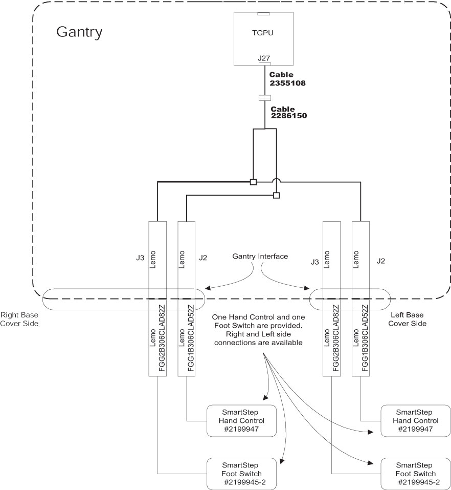
1 Functional Drawing
2 Interconnections
2.1 Installation Faceplates
-
Install the cable 2286150.
-
Connect the LEMO plugs to the right and left option panels.
-
Remove the plate on left side of option interface panel.
-
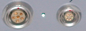
With outer conical nut removed, insert a LEMO connector through the appropriate hole in the faceplate, with the red dot at top. See Figure 1.
Figure 1. Orientation of Connectors
-
Adjust the inside conical nut so enough thread appears through the hole and the external nut can be firmly attached while keeping the connection flush with the faceplate.
-
Repeat steps 1 - 5 (above) for the right-side option interface panel.
-
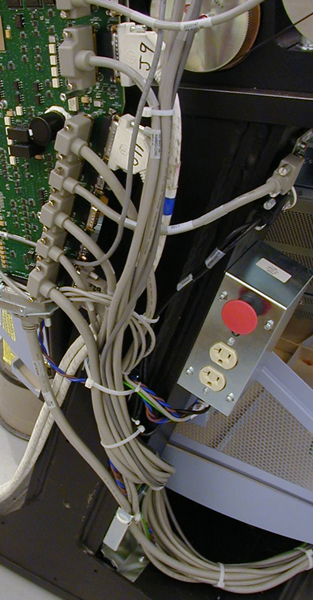
Route the cable as shown in Figure 2 along gantry base’s near tube. Secure cables with ties as shown.
Figure 2. SmartStep Cable Routing
2.2 Installation Cables
-
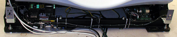
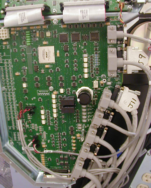
Locate the gantry MSUB (Milwaukee SUBordinate board, which is used to signal routing for the TGP) See Figure 3.
Figure 3. Gantry MSUB
-
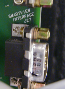
Locate the J27 connector. See Figure 4.
Figure 4. Connetor J27
-
Install the 2355108 cable to the J27 Connector. Ensure that the covers fit around cables. See Figure 5.
Figure 5. 2355108 Cable Installed