- Topic ID: id_15460819
- Version: 2.0
- Date: Nov 8, 2018 1:39:27 AM
Interconnects for SmartStep on CT and PET systems with GOB
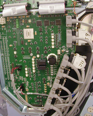
1 Functional Drawing
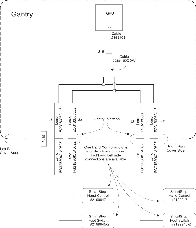
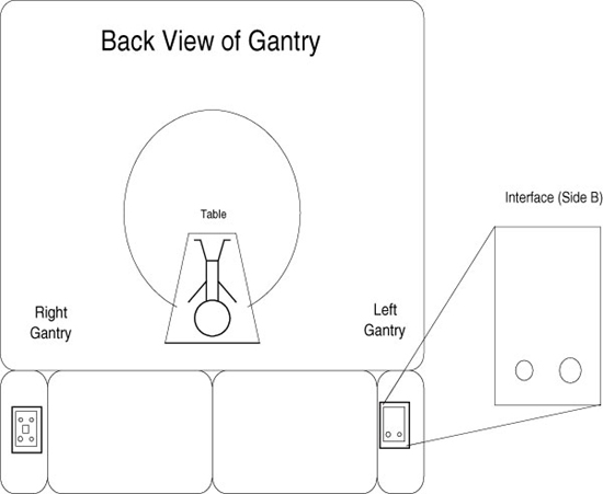
Figure 1. Gantry external connection (back view)
2 Installation - Faceplates
-
Remove existing faceplates - they may be blanks or, if installated, Cardiac Option faceplate.
-
Install the appropriate faceplate at indicated location per the table below using the four nuts removed with the original faceplates (two per faceplate).
-
Install the connector covers to the faceplates using 46-328417P74, 2290289-2, and 2290289 for each side’s faceplate.
-
Layout, but do not yet mount, the included cable (2286150) along the rear cross-tube of the gantry so the connectors can reach both faceplates.
-
Attach the SmartStep cable to the faceplate as follows:
-
With the outer conical nut removed insert a LEMO connector through the appropriate hole in the faceplate, with the red dot facing at the TOP.
-
Adjust the inside conical nut so there is enough thread appearing through the hole to attach the external nut while keeping the connection flush with the faceplate.
-
Repeat for the other three LEMO connectors.
-
-
Using the provided M4 screw (46-328417P4), washer (46-328430P2) and lock washer (46-328432P2), attach the SmartStep cable ground wire to the cable tie screw hole on the chassis. Remove paint as necessary to ensure a good electrical connection.
Figure 2. Ground Wire Installation (Arrow on Rght) Smart Step connectors (Arrow on Left)
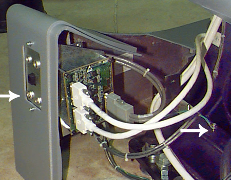
-
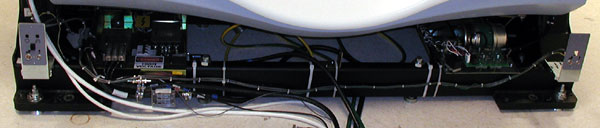
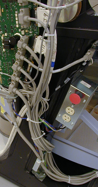
Route the cables and secure with ties as shown in Illustration.
3 Installation - Cables (LS16, Pro16, VCT and VCT64 with GOC6)
-
Locate the gantry MSUB.
-
Locate the J27 Connector.
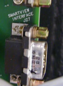
-
Install cable 2355108 to J27 Connector.
-
Connect the other end to gantry cable 2286150, J15.
-
Carefully route the cable along the gantry stationary frame.
-
Check to ensure the covers fit around the cables.