
- SIGNA™ Hero 3.0T Service Methods
- 5852800-8EN Revision 1.0
- 00000018WIA30011E20GYZ
- id_131064166.0
- Feb 21, 2021 9:07:59 PM
UPM Calibration and UPM Functional Check–Body Mode
Prerequisites
| Required persons | Preliminary requirements | Procedure | Finalization |
|---|---|---|---|
| 1 | - | 30 minutes (plus 30 minutes for Agilent wattmeter power up) | 5 minutes |
| Item | Quantity | Effectivity | Part number | Manufacturer |
|---|---|---|---|---|
| Medium Phillips screwdriver | 1 | - | - | - |
| 12 inch crescent wrench | 1 | - | - | - |
| RF power measurement kit (one of the following options): | 1 | - |
EITHER 5307511-2 or 5307511-3 (Bird wattmeter) BOTH 5434817 (Agilent wattmeter) and 5434817-20 (dummy load) | - |
| ||||||||||||||||
| Condition | Reference | Effectivity |
|---|---|---|
|
When using the Agilent wattmeter, plug in the wattmeter and turn it on. The wattmeter must be powered for at least 30 minutes for stable and accurate readings. | - | - |
About this task
This procedure covers the set up and execution of the UPM calibration and UPM functional check for body mode. These procedures must be performed in sequence:
-
The UPM calibration adjusts digital attenuator values internal to the UPM to match the expected RF signal levels.
Calibration is performed for forward power and reflected power for body channel 1 and body channel 2.
-
The UPM functional check runs a prescribed scan in the forward power chain. It compares the measured RF power from the UPM to the expected value stored in the UPM configuration file. If two values are outside 12%, the functional check fails. If the measured RF power exceeds the trip limit, the UPM stops scanning.
The UPM functional check runs a prescribed scan in the reflected power chain, using the same test as forward power.
Dual drive RF amplifier systems operate in average power mode. Functional check tests include: 10-second average power check, RF inhibit test, and short-term average power fault host trip test.
| Calibration Steps | |
| Safety | |
| Body 1 | Disabling T/R, DD, and RF Input for Body Mode |
| Hardware Setup for RF Body 1 Calibration | |
| Calibrating UPM Reflected Power for Body Channel 1 | |
| UPM Functional Check for Body Channel1 | |
| Body 2 | Setting up and Calibrating UPM Forward Power for Body Channel 2 |
| Calibrating Reflected Power for Body Channel 2 | |
| UPM Functional Check for Body Channel 2 | |
| Finalization | |
If you are performing an initial installation and need to calibrate the RF amplifier, calibrate the UPMs, and check the UPMs, use the procedures in RF Amplifier and UPM Calibration.
Disabling T/R, DD, and RF Input for Body Mode
Procedure
- Set Driver Module and Exciter switch per following steps.
Figure 1. Driver Module and Exciter switch setup 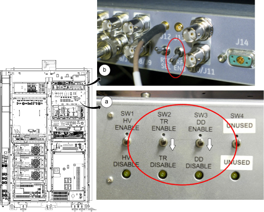
Hardware Setup for RF Body 1 Calibration
Procedure
Calibrating UPM Forward Power for Body Channel 1
Procedure
- Set RF ENB to ENABLE (up).
Figure 2. Exciter switch 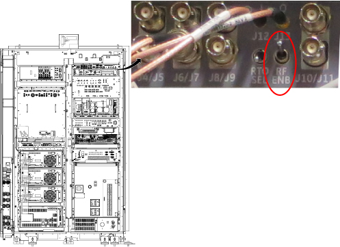
- Press Landmark. Then, advance to scan. A phantom is not needed.
Figure 3. Adv to scan 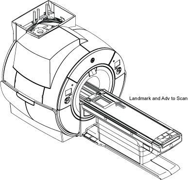
- Make the following selections for the settings.
Figure 4. UPM Calibration Settings 
For this setting: Select: Nuclei 1H Task Calibrate UPM RF Chain Body Channel 1 Power Type Forward
Calibrating UPM Reflected Power for Body Channel 1
About this task
After calibrating forward power, calibrate reflected power as follows.
Procedure
- Disconnect the RF dummy load per following steps.
- Set RF ENB to DISABLE (down).
- Disconnect the RF dummy load from BODY RF OUT J4 for the body channel 1.
- Set RF ENB to ENABLE (up).
Figure 5. Disconnect J4 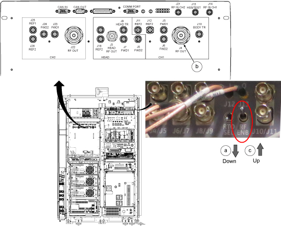
- From the UPM Tool, make the following selections:
Figure 6. UPM Tool Selections for Dual Drive RF Amplifiers 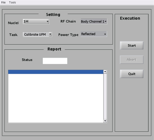
For this setting: Select: Nuclei 1H Task Calibrate UPM RF Chain Body Channel 1 Power Type Reflected - Reconnect coupler to J4 per following steps.
- Set RF ENB to DISABLE (down).
- When the body channel is calibrated (PASS) for reflected power, reconnect the coupler to RF amplifier body channel 1 port (J4). The stub cable remains connected to J22.
- Set RF ENB to ENABLE (up).
Figure 7. Reconnect Coupler to J4
UPM Functional Check for Body Channel1
About this task
After completing the UPM calibration, continue with the UPM functional check.
Procedure
- From the UPM Tool, make the following selections:
Figure 8. UPM Functional Check Selections for Dual Drive RF Amplifiers 
For this setting: Select: Nuclei 1H Task UPM Func Chk RF Chain Body Channel 1 Note: Power Type is grayed out. This is normal and is not used. - Prompts are displayed during test execution, including a popup message about the UPM tripping and a power trip error message. The tool performs three tests before the host trip. This takes 2 to 3 minutes before any user interaction is required.
From the CSD, open the error log. Verify the error log contains the message that the UPM has “detected a power fault on Body Short Term Average.” Select Yes if an error message is displayed.
Figure 9. UPM Power Trip Error Log 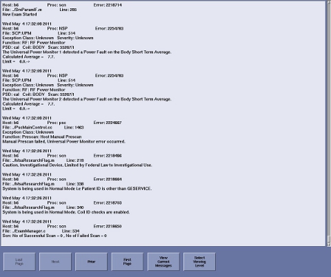
Setting up and Calibrating UPM Forward Power for Body Channel 2
Procedure
- Setup hardware per following steps.
Figure 10. Hardware Setup for RF Body 2 Calibration 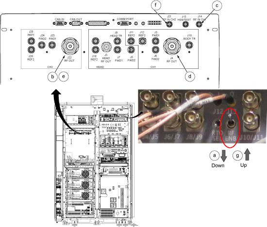
- On the UPM Tool, make the following selections:
Figure 11. Body Mode (Channel 2) Settings 
Settings Value Nuclei 1H Task Calibrate UPM RF Chain Body Channel 2 Power Type Forward
Calibrating Reflected Power for Body Channel 2
About this task
After calibrating forward power, calibrate reflected power as follows.
Procedure
- Setup hardware per following steps.
- Set RF Enable to DISABLE (down).
- Disconnect the RF coupler from BODY RF OUT J22 and set it aside. This part of calibration is performed with no connection to this port. The stub cable on J4 remains connected.
- Set RF Enable to ENABLE (up).
Figure 12. Disconnect J22 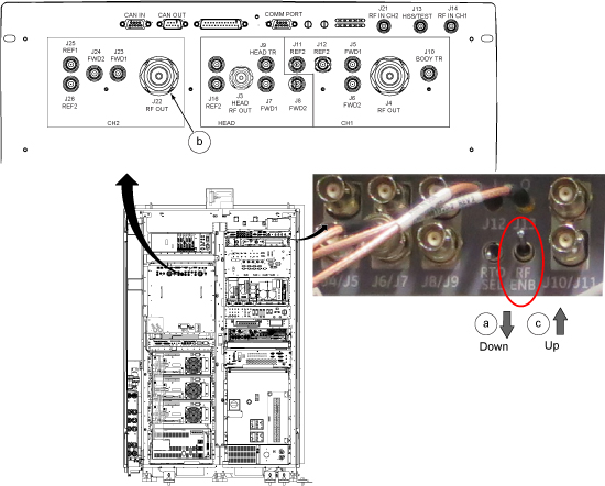
- On the UPM Tool, make the following selections:
Figure 13. UPM Functional Check Selections for Body Channel 2 Reflected 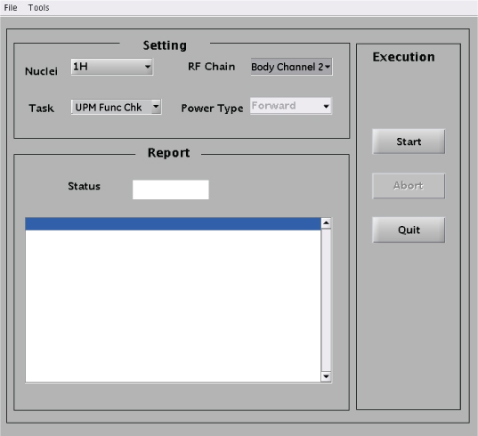
Settings Value Nuclei 1H Task Calibrate UPM RF Chain Body Channel 2 Power Type Reflected - When body channel 2 is calibrated (PASS) for reflected power, return the cable configuration to support testing for forward power:
- Set RF Enable to DISABLE (down).
- On the front of the RF amplifier, reconnect the RF coupler to BODY RF OUT J22.
- Set RF Enable to ENABLE (up).
Figure 14. Reconnect J22
UPM Functional Check for Body Channel 2
Procedure
On the UPM Tool, make the following selections:Notice Figure 15. UPM Functional Check Selections for Body Channel 2 For this setting: Select: Nuclei 1H Task UPM Func Chk RF Chain Body Channel 2 Note: Power Type is grayed out. This is normal and is not used.- Prompts are displayed during test execution, including a popup message about the UPM tripping and a power trip error message. The tool performs three tests before the host trip. This takes 2 to 3 minutes before any user interaction is required.
From the CSD, open the error log. Verify the error log contains the message that the UPM has “detected a power fault on Body Short Term Average.” Select Yes if an error message is displayed.
Figure 16. UPM Power Trip Error Log - Restore the Body RF cables per following steps.
- Set RF Enable to DISABLE (down).
- Disconnect the 3/16-Wavelength Cable Stub from J4and set it aside. Reconnect the system body channel 1 transmit cable to RF amplifier body output channel 1 RF OUT J4.
- Disconnect the coupler from RF amplifier channel 2 RF OUT J22 and set it aside. Reconnect the system body channel 2 transmit cable to RF amplifier body output channel 2 RF OUT J22.
- Reconnect body channel 1 BNC input cable with cable labeled "J14" to BNC RF input port J14 on the front of the RF amplifier.
- Set RF Enable to ENABLE (up).
Figure 17. Restore the Body RF cables 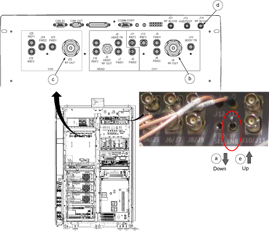
Finalization
Procedure
- Confirm that the other RF amplifier system cables are reconnected to their correct locations for clinical scanning.
- Complete a TPS reset and perform Check Scan.
- If all the calibrations have been successfully made, perform a SaveInfo to save the UPM calibration results.