Agilent Wattmeter and Power Adjustment Kit for RF Body Calibration
Prerequisites
Table 1. Personnel requirements
Required persons
Preliminary requirements
Procedure
Finalization
1
Not Applicable
Part of parent procedure minutes
Not Applicable
Topic ID: id_SL13643076-1274797
Agilent Wattmeter Setup
About this task
The Agilent wattmeter must be powered on for at least 30 minutes
for stable and accurate readings. Plug in the wattmeter and turn it
on at the beginning of this procedure.
Procedure
CAUTION
Possible equipment damage!
Physical shocks to the sensor and coupler (for instance,
dropping them) can damage them or cause them to go out of calibration.
Take care when handling the coupler and adapter. When connecting
to the sensor, hold the sensor steady and turn the knurled rings on
the connectors to tighten them. Take care not to cross-thread the
sensor connections.
Notice
Make sure the serial numbers for the RF coupler and RF sensor match each other. They are calibrated together, and should not be swapped between power measurement kits.
Set up the wattmeter for calibration as shown in the following
illustration.
Connect the Agilent sensor probe cable to the sensor.
Connect the sensor to the power reference (PWR REF) port on the wattmeter.
Connect the other end of the sensor probe cable to the Channel A port on the wattmeter.
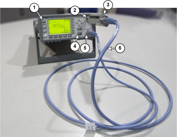
Figure 1. Agilent Wattmeter Calibration Setup
1
Front of wattmeter
4
Zero/Cal button
2
Power reference (PWR REF) port
5
Channel A port
3
Agilent RF power sensor
6
Agilent sensor probe cable
On the front of the wattmeter, press Zero/Cal.
Press the Zero + Cal softkey to start
the calibration process.
The wattmeter displays a wait screen while it zeros. While the
wattmeter calibrates, a green LED next to the power reference port
turns on (indicating RF power is being transmitted from the reference
port). When this LED turns off, the calibration is complete.
If there is a calibration error, an error message appears on
the wattmeter screen. If this happens, check the connections to the
meter and sensor and press the Zero + Cal softkey
to re-run the calibration.
Note:
Expect to see a fluctuating low power reading on the wattmeter
on the order of ±3.0 dBm (± 2.0 mW) after it is calibrated.
Topic ID: id_SL13643077-1274797
Wattmeter and Dummy Load Setup for Body Mode
Procedure
DANGER
FATAL ELECTRIC SHOCK HAZARD.
THE RF AMPLIFIER IS NOT DISABLED.
TO PREVENT FATAL ELECTRIC SHOCK, ENSURE THE RF AMPLIFIER
IS DISABLED WHILE CONFIGURING THE CALIBRATION TOOLS.
CAUTION
Electrical/RF burn hazard
RF burns can occur as a result of disconnecting heliax cables while the system is scanning.
To prevent possible RF burns when disconnecting heliax cables from the RF amplifier, make sure that the system is not manually prescanning or scanning. Make sure that the scan desktop icon displays the “idle” message and the RF enable switch is in the “off” position.
Notice
Possible equipment damage. Do not connect/disconnect the wattmeter sensor while the meter is ON. Always turn the meter OFF before plugging/unplugging the sensor.
Verify that the scanner is idle. Confirm that the RF ENB switch
on the DTX1 exciter is in the Disable (down) position.
CAUTION
Equipment Damage!
If the body coil is connect to the RF amplifier and the
wrong channel is selected, damage to the DTRSW can occur.
Disconnect the unused body channel during testing and calibration
of the RF amplifier.
Setup the hardware per following steps.
Disconnect both channel 1 and 2 body output cables (at J4 and J22) from the front panel
of the RF amplifier and set both aside.
Disconnect the cable J21 (RF input for
body channel 2) from the body channel input BNC on the front panel
of the RF amplifier.
Attach the 3/16-Wavelength Cable Stub (part of the RF Power
Measurement Kit) to body channel output J22 to cover exposed RF port that is not being tested.
Note:
The 3/16-Wavelength Cable Stub is used as a safety measure
to cover and prevent contact with an exposed RF connector. It is not
required for successful calibration.
Connect the input of the coupler to RF amplifier J4.
Note:
This arrangement will remain in place during UPM calibration
and functional check for channel 1 ONLY.
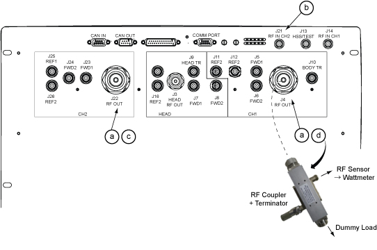
Figure 2. Hardware setup at RF Amp
Topic ID: id_SL13643078-1274797
Setting up Agilent Wattmeter to Measure Forward Body Maximum
Power
Procedure
Warning
Electric shock risk!
pay close attention to the connections to the dummy load.
Failure to connect the dummy load correctly could result in electric
shock.
Use a digital multimeter to measure the resistance between the
dummy load RF connector center pin and the shield. Confirm a reading
of 50 ohms (+/- 5 ohms). Replace the dummy load if the resistance
is out of range.
Connect the remaining Agilent power components as shown below.
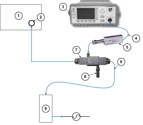
Figure 3. Agilent Power Meter Setup for RF Body Calibration
1
RF amplifier (front)
6
RF cable to dummy load
2
RF output port
7
RF coupler
3
Wattmeter
8
Agilent 50 ohm terminator connected to the Reflected port on the coupler
4
Agilent sensor probe cable
9
Dummy load with internal fans
5
RF sensor connected to the Incident port
on the coupler
Connect one end of the RF sensor to the wattmeter. Connect the
other end to the coupler.
Notice
Do not apply RF power to the dummy load without its fan in operation. Doing so will result in catastrophic damage to the dummy load due to overheating.
Plug the fan for the dummy load into a service outlet located
in the lower right part of the ISC. Never use
this dummy load without its fan running.
CAUTION
Possible equipment damage!
Physical shocks to the sensor and coupler (for instance,
dropping them) can damage them or cause them to go out of calibration.
Take care when handling the coupler and adapter.
Notice
Make sure the serial numbers for the RF coupler and RF sensor match each other. They are calibrated together, and should not be swapped between power measurement kits.
When the power meter has started, press Preset/Local.
Select Default, and then press Confirm.
Press System.
Press Save/Recall.
The meter displays a list of predefined applications.
(For dual drive RF amplifiers) The meter displays
a list of predefined applications. Use the up and down cursor keys
to highlight 3T_Dual_Body. Use this setting for
both body channel 1 and body channel 2.