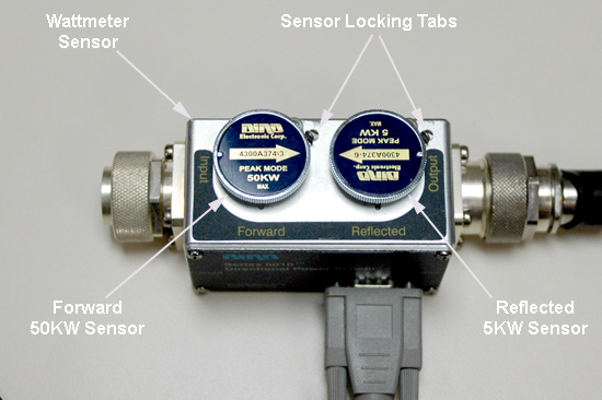
Insert the 50 kW element into the Forward sensor port (blue
4300A374-3). Lock the element in place using the locking tab on the
sensor.
The Reflected port is not used during this procedure. Placing
the 5000 W element (blue 4300A374-6) into the Reflected port is just
a safety measure, and is not used during body calibration.
Make sure the arrows on the elements point in opposite directions.
Figure 1. RF Coupler Setup for Body Mode
Use the DVM to measure the resistance of input to the dummy
load. Confirm that the resistance measures 50 ohms +/- 5 ohms.
Note:
If the dummy load is out of spec, return the RF kit for
repair. Do NOT proceed with the RF amplifier output calibration.
Topic ID: id_SL13643031-1274795
Wattmeter and Dummy Load Setup for Body Channel 1
Procedure
DANGER
FATAL ELECTRIC SHOCK HAZARD!
THE RF AMPLIFIER IS NOT DISABLED.
TO PREVENT FATAL ELECTRIC SHOCK, ENSURE THE RF AMPLIFIER
IS DISABLED WHILE CONFIGURING THE CALIBRATION TOOLS.
Warning
ELECTRICAL/RF BURN HAZARD!
RF BURNS Can Occur AS A RESULT OF DISCONNECTING HELIAX CABLES
WHILE THE SYSTEM IS SCANNING.
PREVENT POSSIBLE RF BURNS WHEN DISCONNECTING HELIAX CABLES
FROM THE RF AMPLIFIER BY VERIFYING THAT THE SYSTEM IS NOT MANUALLY
PRESCANNING OR SCANNING. VERIFY THAT THE SCAN DESKTOP ICON DISPLAYS
THE “IDLE” MESSAGE AND THE RF ENABLE SWITCH IS IN THE
“OFF” POSITION.
Notice
Possible equipment damage. Do not connect/disconnect the wattmeter sensor while the meter is ON. Always turn the meter OFF before plugging/unplugging the sensor.
Verify that the scanner is idle. Confirm that the RF ENB switch
on the DTX1 exciter is in the Disable (down) position.
CAUTION
Equipment Damage!
If the body coil is connect to the RF amplifier and the
wrong channel is selected, damage to the DTRSW can occur.
Disconnect the unused body channel during testing and calibration
of the RF amplifier.
Setup the hardware per following steps
Disconnect both channel 1 and 2 body output cables (at J4 and J22) from the front panel
of the RF amplifier and set both aside.
Remove cable J21 (RF input for body channel
2) from the body channel input BNC on the front panel of the RF amplifier.
Attach the 3/16-Wavelength Cable Stub (part of the RF Power
Measurement Kit) to body channel output J22 to cover exposed RF port that is not being tested.
Note:
The 3/16-Wavelength Cable Stub is used as a safety measure
to cover and prevent contact with an exposed RF connector. It is not
required for successful calibration.
Connect the input of the coupler to RF amplifier J4.
Note:
This arrangement will remain in place during UPM calibration
and functional check for channel 1 ONLY.
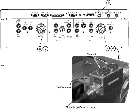
Figure 2. Hardware setup at RF Amp
Warning
Electric shock risk!
Failure to connect the dummy load correctly could result
in electric shock.
pay close attention to the connections to the dummy load.
Connect the output of the RF coupler to the dummy load.
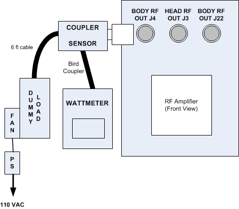
Figure 3. Complete Body Output Test Setup for Dual Drive Amplifier
Plug in the wattmeter to use wall power (batteries are often
not charged). Connect one end of the wattmeter cable to the sensor
connector (RS232 is unused). Connect the other end to the coupler.
Notice
Do not apply RF power to the dummy load without its fan in operation. Doing so will result in catastrophic damage to the dummy load due to overheating.
Plug the fan for the dummy load into a service outlet located
in the lower right part of the ISC. Never use
this dummy load without its fan running.
Set the RF ENB switch to ENABLE (up).
Topic ID: id_SL13643032-1274795
Setting up Bird 5000-EX Wattmeter to Measure Forward Body Maximum
Power
About this task
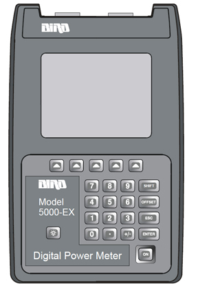
This procedure is for the Bird 5000-EX.
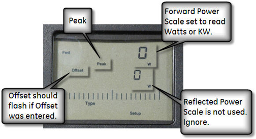
Figure 4. Bird 5000-EX Wattmeter
Procedure
Press the ON button on the wattmeter.
(If the coupler and sensor are not correctly attached to the amplifier
you will see a “No Sensor” indication.)
Select the arrow ▲ button under Scale.
Enter 50000 to set the range.
Select the ENTER button.
Check the setting by selecting the arrow button under Scale.
Press the ENTER button to exit.
Select the arrow button under Fwd Units. Make sure the scale reads W (or kW“on
some wattmeters). If the scale reads dBm, select the arrow button
under Fwd Units again to toggle the scale to
read W (Watts) or kW (kiloWatts) on the TOP,
forward power scale. Ignore the BOTTOM, reflected power scale value.
It is not used during maximum power calibration.
Select the SHIFT button.
Select the arrow button under Setup.
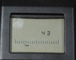
This displays the sensor type configured in the wattmeter. This
procedure uses sensor type 43, which is optimized for peak power measurement.
Verify that the output reads 43, and
then press the ENTER button.
Figure 5. Wattmeter Display Set to Read
Press the ENTER button.
Press the arrow ▲ button under Type and
then toggle to change the unit of measurement to Peak.
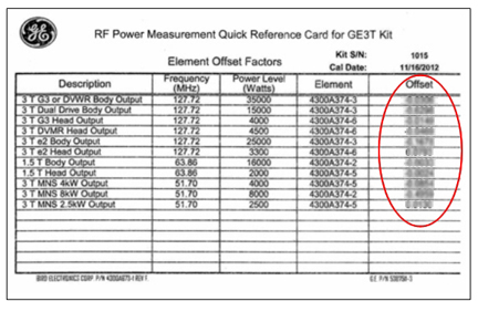
All kits require an offset to ensure accurate measurement. Locate
the Element Offset Factors card in the kit.
Find the offset for “3T Dual Drive Body Output”.
Figure 6. Example Element Offset Factors Card
Press the Offset button on the wattmeter.
Enter the numerical value from the offset card and press the Enter button.
Note:
To enter a negative value, first enter the numerical value,
then the minus symbol (–).