
- SIGNA™ Hero 3.0T Service Methods
- 5852800-8EN Revision 1.0
- 00000018WIA30570110GYZ
- id_20033079.21
- Dec 3, 2021 4:57:24 PM
System and hardware configuration
This topic describes the values and explanation of each parameter for system configuration and hardware configuration in Guided Install.
The MR System is configured for the various hardware interactions within the system using the Guided Install System Configure and Hardware Configure tabs.
Below are the examples of the System Configure and Hardware Configure tabs, respectively (these are only examples and are subject to change based on software revision).
The following table provides guidance to fill out the various system configuration parameters.
| Parameter | Explanation | Value |
|---|---|---|
| Hospital Name | Enter the name of the hospital or site that will appear at the top of filmed images. | Site-entered |
| Suite_ID | Enter the name of the suite to which the scanner will be connected. If the system is connected to a suite of systems, the name may need to be acquired from the site's system administrator. If the system is stand-alone (not connected to a suite or hospital network), the name is at the option of the installer. | Site-entered |
| Host_ID | Enter the name of the system host. If the system is connected to the site's network, the name may need to be acquired from the site's system administrator. If the system is a stand-alone (not connected to a suite or hospital network), the name is at the option of the installer. | Site-entered |
| Unique / System ID | This is the GE CARES Unique system ID. This information is generated through the GEMS local area service manager. A dummy ID can be entered if the correct ID is unknown to speed up installation. The installer can go back and update this field with the correct code later when the correct information is known. An example of a dummy ID could be 123. | Site-entered |
| Service ID | This is the GE CARES System ID. This information is generated through the GEMS local area service manager. A dummy ID can be entered if the correct ID is unknown to speed up installation. The installer can go back and update this field with the correct code later when the correct information is known. An example of a dummy ID could be 123. However it should be noted that the entire GE back office connectivity suite, including Remote Software Download (RSD), is highly dependent on this entry being accurate. | Site-entered |
| Date Format | This is the date structure to be used/displayed by the system. A choice of one of six options are available. Each with date format and standard time (AM/PM) or military time (24 hour clock). Japanese ERA time format is also provided. | (MMM DD YY AM/PM) [(MMM DD YY AM/PM), (DD MMM YY AM/PM), (YY MMM DD AM/PM), (MMM DD YY 0-23), (DD MMM YY 0-23), (YY MMM DD 0-23)] |
| Weight Unit | Select the unit of measurement desired by the site's staff: kilograms or pounds. | Pounds (Pounds, Kilograms) |
| Keyboard | Choose the keyboard language that will be used for this system. | American (American, French, German, Italian, Portuguese, Spanish, Swedish, Danish, Dutch, Norwegian, Finnish) |
| Language | Choose the language that will be used where the system is being installed. | English (English, French, German, Italian, Portuguese, Spanish, Japanese, Chinese, Danish, Dutch, Norwegian, Finnish, Swedish) |
| Video Card | Video card value is selected automatically. | N/A |
| Display Type | LCD Monitor - Other is selected as default. | LCD Monitor - Other |
| Legacy Image Type | Legacy Image Type: Select the legacy image type for the system being installed: Yes, No. | Yes (Yes, No) |
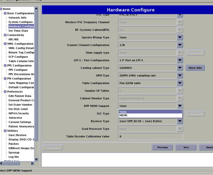
The following table provides guidance to fill out the various hardware configuration parameters.
The Guided Install Product Based Selection feature lets you select the product that you are installing during the Load From Cold procedure. The fields in the Guided Install hardware tab are automatically populated based on the product that you select.
| Parameter | Explanation | Value |
|---|---|---|
| Product Name | Select the product name for the product being installed. | SIGNA Hero |
| Field Strength | - | 3.0T |
| Package Name | Gradient driver-coil package name. | SSSD |
| Gradient Type | Gradient driver type. | 5550 (SSSD) |
| Resonance Module | Gradient coil type. | VRMW |
| Magnet Serial Number | Enter the magnet serial number for the installed system. The serial number can be found on the rating plate on the magnet. | Enter the magnet serial number that starts with UA, AR, or AC. |
| Magnet Ramp Direction | - | Forward |
| Table Limit | - | Auto-populated |
| Scan Range |
Long is the default value. With the table at the end of travel, the minimum distance between the cradle edge and wall should be greater than 25 mm for the long range. If it is not, select short range. Confirm the final selection with your Project Manager of Installation (PMI). Select short if there is not enough room for the cable overhang between the rear pedestal and the customer wall. |
Long Short |
| Line Frequency | Select the incoming power line frequency under which the installed site will operate. Selections are:
|
60 Hz 50 Hz |
| RF Amp Type | - | 3.0T 30 KW dual drive RF amp |
| Number of Tx Channels |
Select the number of RF transmit channel on the system Note: This field is available on PX29 and later software releases only.
| 2 |
| Governing Body | Select the governing body according to the Region rule. Selections are:
| fda2, iec, MHLW-JIS, special1, special2 |
| ISO Vector Z | Enclosure and Iso-Z value. | 3.0T 70 cm magnet enclosure |
| Magnet Enclosure | - | Rio 12.1 for Hero configuration |
| PAC Type | - | PAC2B/PAC5 |
| Wireless PAC Frequency Channel | Field is available on PX29 and later software. This is non-editable and is built in for future use. | None |
| RF-Systems Cabinet (RFS) | Yes is the default value. | Yes |
| Spectro RFamp Type | Not used on Pioneer or Hero. | None |
| Scanner Channel Configuration | Select the channel configuration as applicable. Note: Some channel configurations may require option keys. |
|
| Shim Supply Type | None is the default value. Select NAV Shim Supply if the system is configured with HO Shim. | None |
| LPCA/Port Configuration | - | 3 P-ports + PA-port |
| HEC Type/Cooling Cabinet Type | - | 5453786 |
| Table Configuration | - |
|
| Number of Tables | This field is available on PX29 and later software and can be either 1 or 2 tables, no other selection is available. | 1 or 2 |
| Cabinet Monitor Type |
Configures the version of Cabinet Monitor installed on the system. Select the correct one installed on the system. |
Cabinet Monitor 3 |
| DPP MEMs Support | HERO does not include a MEMs power supply. | Default is "None". |
| UPM Type | - | QUPM 1 MHz sampling rate |
| SSC Type | - | ICE |
| Receiver Type |
Identify the Gen2 DS DPP RCVR and Gen2 DS RxDist by part numbers 5789759 and 5434906-2, respectively Identify Gen2 DPP RCVR and Gen1 RxDist by part numbers 5641325 and 5434906-2, respectively Identify Gen1 DPP RCVR and Gen1 Rx Dist by part numbers 5503386 and 5434906, respectively |
Gen2 DS DPP_RCVR + Gen2 DS RxDist |
| Grad Processor Type | - | None |
| Table Encoder Calibration Value | See Installing the string encoder for finding the label on the string encoder. | Check encoder and write down specific value |
| Table Encoder Calibration Value 2 | Enabled only if two detachable (dockable) tables are configured in the Number of Tables field. See Installing the string encoder for finding the label on the string encoder. | Check encoder and write down specific value |
| Bridge Type | Not selectable. | 1-Piece Bridge |
| Altitude in Meters | The altitude of the installation site determined using a website. To determine the altitude, see:
| -500m to + 5000m Note: For Hero systems with software version 29.1, this tab is not editable in Guided Install. |
| Parameter | Explanation | Value |
|---|---|---|
| Host IP Address | Main IP address used for interfacing with the web. | Site-entered |
| Netmask | Mask for network of devices in network. | Automatically entered |
| Hostname | Displayed name of the device seen by other connected devices. | Site-entered, consult with customer on what the scanner is named |
| Magnet Monitor IP Address | Address for magnet monitor. | Site-entered from monitor |
| FE Laptop IP Address | Address for service laptop. | Entered from computer |
| TPS/MGD Subnet | Address for TPS or MGD, address internal to local network. | To set to correct value, type 0.0.0. A window will display, with suggestions of the valid choices for addresses. |
| Default Router IP Address | IP address for the router used in the system to interface with the internet. | Taken from router |
| NTP Server IP Address | Server address for NTP. | Site-entered |