XFD-PS Replacement (Mobile Site)
Prerequisites
1 Remove XFD-PS
Procedure
- Remove L Upper Front Cover. Refer to SC Cover Removal
- notice
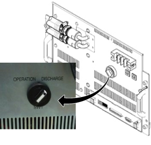
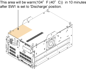
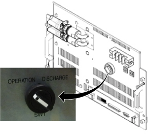
- Turn the SW1 to Discharge on Front .
Figure 1. Discharge
- Drain the coolant. Refer to Draining Operation before replacing SRFD3, XFA, or XFD-PS.
 warning
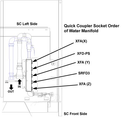
- Disconnect the IN and OUT quick couplers of XFD-PS from the
water manifold.
Figure 2. Water Manifold Socket Order
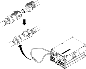
 note: When disconnecting the quick couplers, move the couplers in parallel not to damage it.
 - caution
- Connect the IN and OUT of quick coupler.
Figure 3. Water Manifold
- Set the Universal Lift Hoist onto SC top. Refer to Hoist Setup.
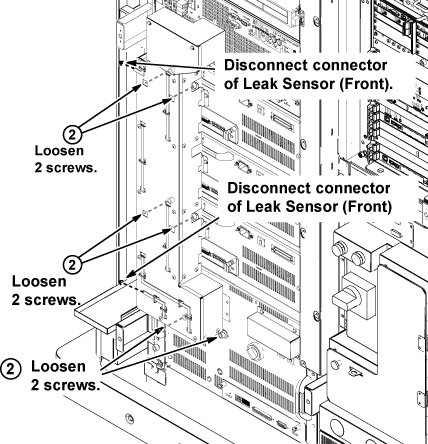
- Disconnect the two connectors of leak sensor assy.
- Remove the cabinet leak sensor assy by loosening 6 screws.
Figure 4. Remove Leak Sensor
- Disconnect the cable from J2 at Control Board and 4 terminal cables.
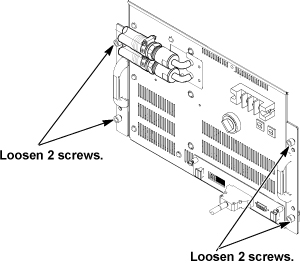
- Loosen 4 screws which are tightening XFD-PS front panel to
the chassis.
Figure 5. Remove Terminal Cover
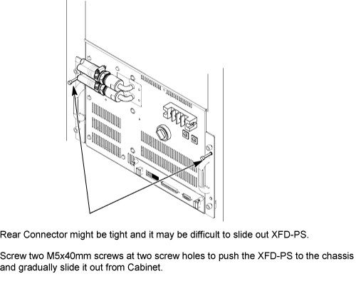
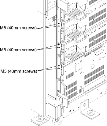
- Screw two M5 (40mm) screws at the two screw holes to push the
XFD-PS to the chassis and gradually slide it out from Cabinet.
Figure 6. Gradually Slide Out Using Screws
 note: If you cannot withdraw XFD-PS using M5 screw, need to disconnect connector from rear side. Refer to In case connector of XFA or XFD-PS is very tight.
 - Withdraw XFD-PS from the chassis.
- notice
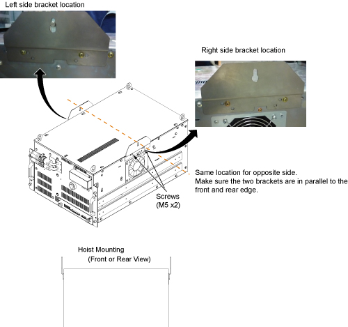
- Install hoist brackets to the chassis of XFD-PS with 4 screws.
Do not tighten 4 screws of hoist brackets.note: Hoist Bracket is stored in FRU box.
Figure 7. Hoist Brackets Installation
- Install the hoist assembly to the hoist brackets of XFD-PS, and tighten 4 screws of hoist brackets. Check that hoist bracket and hoist assembly are installed surely.
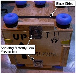
- Remove the top from the FRU case by releasing the butterfly
clamp on each side.
Locate the top of FRU Box under the XFD-PS.
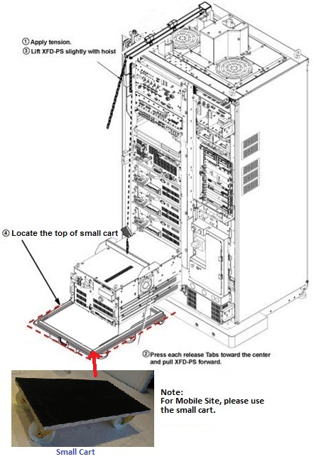
- Using the hoist, apply tension to the lifting chain until the weight of the XFD-PS is supported by the hoist.
- Press the release tabs in on each side as you pull the unit
out further.
Figure 8. Hoist Operation of XFD-PS
- notice
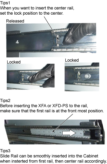
- Push the rail slider into the system cabinet before lowering
XFD-PS. note:
Here is the tips of slider rail operation.
- caution
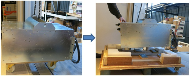
- Lift the XFD-PS up slightly to place the top of the small cart.
- Use the hoist and slowly lower the XFD-PS Chassis to the top of the small cart.
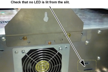
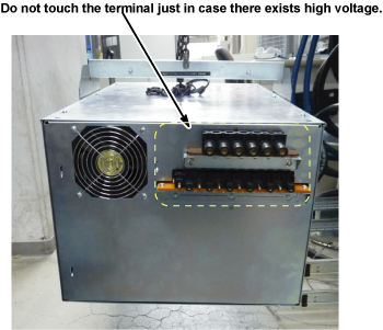
- Check that no LED is lit from the slit of right panel. If any
LED is lit, Switch may be in failure and there exists charge inside
of XFD-PS.
Figure 9. LED Check
If LED is lit, check the voltage of rear terminal. See Figure 10.
Figure 10. Rear View of XFD-PS
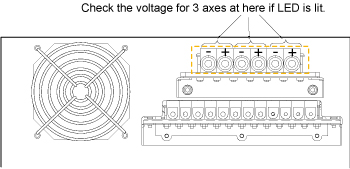
If voltage exist, wait until LED is turned OFF before transferring defective XFD-PS.
At worst case, it will take 1 days to discharge.
note: EDLC (Super Capacitor in XFD-PS) is safe during discharge state unless the terminal is shorted.note: Never short the terminal of XFD-PS. - Move the cart with PS out of equipment room
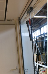
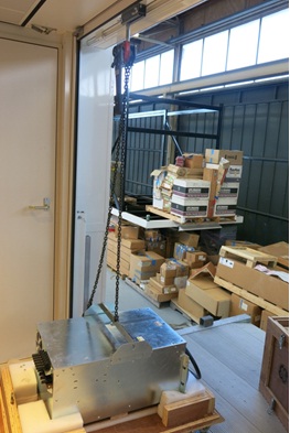
- Install the hoist tool to the hoist point of trailer
Figure 11. Install the hoist tool to the hoist point of trailer
- Hoist the PS from the hoist point of trailer and put onto the
top cover of PS FRU package.
Figure 12. Put XFD-PS to the top of FRU package
- Install the side covers on it
- Uplift and move the PS with package out of the trailer.
Figure 13. Move the PS with package out of the trailer
 |
 |
|
M5 Screws to push out XFD-PS are located at chassis as following illustration.
|
|
2 Install XFD-PS (Mobile Site)
Procedure
- Uplift and move the new XFD-PS FRU with its arms (in side cover) to the hoist position on the trailer.
- Install Hoist tool to connect XFD-PS and hoist point on the trailer.
- Hoist the XFD-PS from the hoist point of trailer.
Figure 14. Hoist XFD-PS
- Put the XFD-PS onto the small cart in the operating room.
Figure 15. Put XFD-PS to small cart
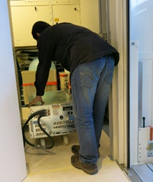
- Move the cart with new XFD-PS to the equipment room
Figure 16. Move new XFD-PS to the equipment room
- Install XFD-PS by the reverse order of the removal. note: Make sure to connect all cables and hoses.note: Make sure to close draining valves and open Supply and Return valves.
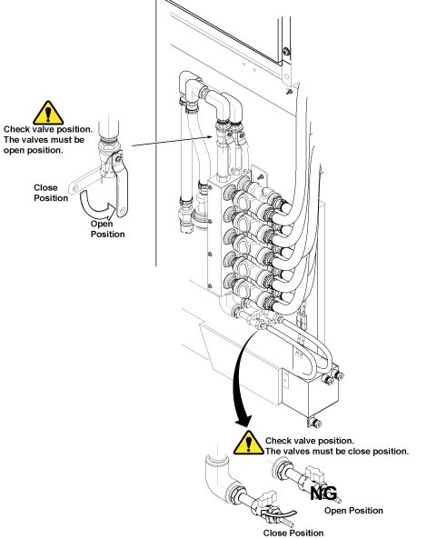
- Be sure to install the hoses to water manifold.
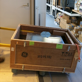
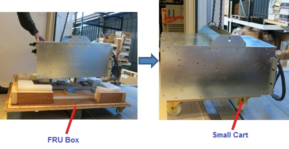
- Restore FRU Box as it was.
Figure 17. FRU Box
- Check that the SW1 is at Operation position.
Figure 18. Operation Position
- Remove the two hoist brackets from XFD-PS chassis.
- Restore System Cabinet.
3 Finalization
Procedure
- Restore the Power. Refer to Lockout / Tagout for MDP(Main Disconnect Panel) or Facility PDU .
- Refill Coolant. Refer to Refill Coolant after replacement of SRFD3, XFA, or XFD-PS.
- Perform Signal to Noise - Head Scan.