Up Limit Sensor
Prerequisites
Procedure
- Move table to near topmost position
- Remove base FRP covers
Figure 1. Remove base FRP covers — 1
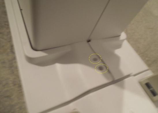
Figure 2. Remove base FRP covers — 2
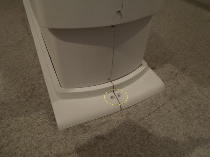
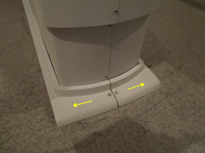
Figure 3. Remove base FRP covers — 3
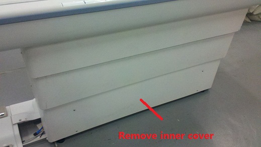
- Disassemble left inner scissor cover
Figure 4. Disassemble left inner scissor cover
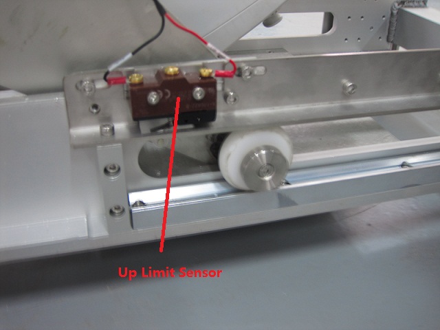
- Replace up limit sensor
Figure 5. Replace up limit sensor
- Move table to topmost position
- Align table height with magnet by adjusting leveling pads
- Restore left inner scissor cover and base covers
Finalization
- Turn the system power ON. Refer to Lockout / Tagout for System Cabinet PDU Main Breaker.
- Level the Table and perform Height Adjustment. Refer to LEVELING FIXED TABLE and TOP HEIGHT ADJUSTMENT.
- Fix the FRP Covers of the Table.
- Perform CRADLE HOME SENSOR CHECK .
- Check the Table Function. Refer to TABLE CHECKS AFTER INSTALLATION .
- Perform Express Coil MCQA Test to check that the PA coil cable is properly connected.