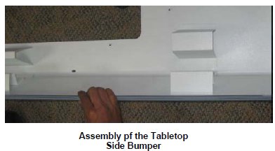
TABLE TOP SIDE BUMPER
Prerequisites
Procedure
- System Power must be turned OFF. Refer to Lockout / Tagout for System Cabinet PDU Main Breaker...
- Disconnect the Table from MR Magnet; take it out from the Magnet
room. Refer to TAKE TABLE OUT FROM THE MAGNET ROOM
- Remove the scissor covers from the table. SCISSOR COVERS
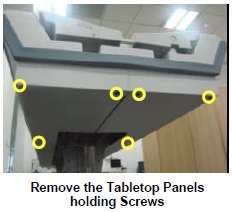
- Remove the marked Screws of the Tabletop Panel LH and RH assembly.
Figure 2. Tabletop Panel
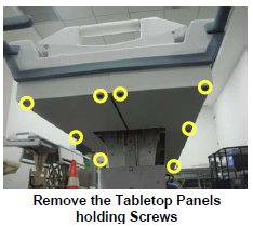
- Remove the marked Screws of the Tabletop Panel LH and RH assembly.
Figure 3. Bent down the Panel LH and RH
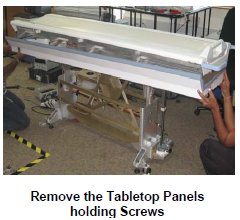
- Push down the Full Tabletop Panel LH and RH in order to remove
the side Bumper.
Figure 4. Remove foot end bumper
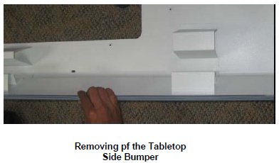
- Remove the Side bumper from the Tabletop Panels.
Figure 5. Bumper to the Tabletop Panels
- Now take the new Side Bumper, fix the Bumper to the Tabletop
Panels.
Figure 6. Fix the Panel LH and RH
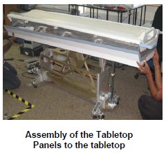
- Fix the Panel LH and RH to the tabletop, such that the Tabletop
FRP will be placed inside the Head end, Foot end and side bumpers.
Figure 7. Fix back the marked Screws
- Tabletop Panel LH and RH assembly.
Figure 8. Fix back the marked Screws
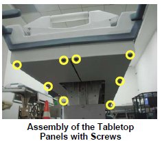
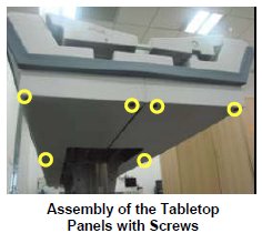
- Fix back the marked Screws of the Tabletop Panel LH and RH assembly.
Figure 9. Fix back the marked Screws
- Level the table.
- Dock centering and Height adjustments.
- Fix the scissor covers from the table.
1 Finalization
Procedure
- Turn On the System Power. Refer to Lockout / Tagout for System Cabinet PDU Main Breaker.
- Level the Table and adjust table height. Refer to LEVELING FIXED TABLE and TOP HEIGHT ADJUSTMENT.
- Fix the FRP Covers of the Table.
- Check the Table Function. Refer to TABLE CHECKS AFTER INSTALLATION .
- Perform Express Coil MCQA Test to check that the PA coil cable is properly connected.