TABLE TOP HEAD END BUMPER
Prerequisites
Procedure
- System Power must be turned OFF. Refer to Lockout / Tagout for System Cabinet PDU Main Breaker...
- Disconnect the Table from MR Magnet; take it out from the Magnet
room. Refer to TAKE TABLE OUT FROM THE MAGNET ROOM
- Remove the scissor covers from the table. SCISSOR COVERS
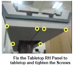
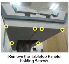
- Remove the marked Screws of the Tabletop Panel LH and RH assembly.
Figure 2. Tabletop Panel
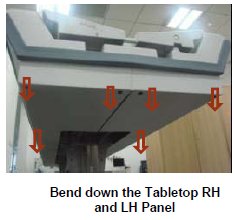
- Bent down the Panel LH and RH in order to remove the Foot end
Bumper.
Figure 3. Bent down the Panel LH and RH
- Remove the foot end bumper from the Tabletop Panels.
Figure 4. Remove foot end bumper
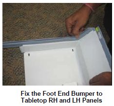
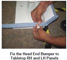
- Now take the new foot end Bumper, fix the Bumper to the Tabletop
Panels.
Figure 5. Bumper to the Tabletop Panels
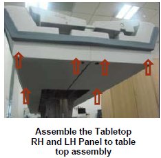
- Fix the Panel LH and RH to the tabletop, such that the Tabletop
FRP will be placed inside the Foot end bumper.
Figure 6. Fix the Panel LH and RH
- Fix back the marked Screws of the Tabletop Panel LH and RH assembly.
Figure 7. Fix back the marked Screws
- Level the table.
- Dock centering and Height adjustments.
- Fix the scissor covers from the table.
1 Finalization
Procedure
- Turn the System Power ON. Refer to Lockout / Tagout for System Cabinet PDU Main Breaker...
- Level the table and adjust top height. refer to LEVELING FIXED TABLE and TOP HEIGHT ADJUSTMENT.
- Fix the FRP Covers of the Table.
- Check the Table Function. Refer to TABLE CHECKS AFTER INSTALLATION .
- Perform Express Coil MCQA Test to check that the PA coil cable is properly connected.