Replacing BRM-D (Short) RF Body Coil
Prerequisites
The RF body coil cartridge is a Field Replaceable Unit (FRU) that mounts inside the gradient coil (also a FRU). It is available in 1.0T and 1.5T versions. If the RF coil fails, it must be removed from the gradient coil and replaced. Since the replacement procedures for the RF and gradient coils are closely related, references are made below to the epoxy-filled gradient coil replacement procedure where instructions for removal of similar parts (for example, the bridge) can be found. While a portion of the following procedure can be accomplished by one person (connecting/disconnecting various cables, etc.), replacing a failed RF body coil requires more than one person.
Only trained and qualified engineer can execute this procedure.
1 Unpacking BRM-D (Short) RF Body Coil
Procedure
- A new Cardiac RF body coil is packed in a shipping container (trunk) that is strapped to a pallet. Unstrap the shipping container from the pallet and remove the RF body coil from the trunk. (The process is reversed when preparing the defective RF body coil for return.)
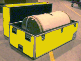
- See Figure 1 through Figure 3 to remove the replacement coil.
Figure 1. Tilt RF Coil Case and Roll Off Pallet
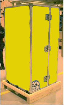
Figure 2. Move RF Coil Case to Final Location and Set Case Horizontally
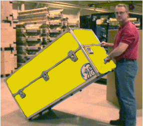
Figure 3. Open RF Coil Case and Remove New Coil
2 Replacing BRM-D (Short) RF Body Coil
Procedure
- Remove the RF Body coil from the CRM without using the RF tracks,
which are too thick to use. Use pieces of smooth, stiff material (sheets
of film work well) to easily slide the RF coil out of the Gradient
Coil. See Figure 4 through Figure 14 for removing and replacing the BRM-D RF Body Coil.
Figure 4. Loosening BRM-D (Short) RF Body Coil Overview
Figure 5. Loosening BRM-D (Short) RF Body Coil Detail
Figure 6. Release the Latch Assembly
Figure 7. Latch Assembly Detail
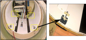
Figure 8. Release the RF Constraints
Figure 9. Removing BRM-D (Short) RF Body Coil
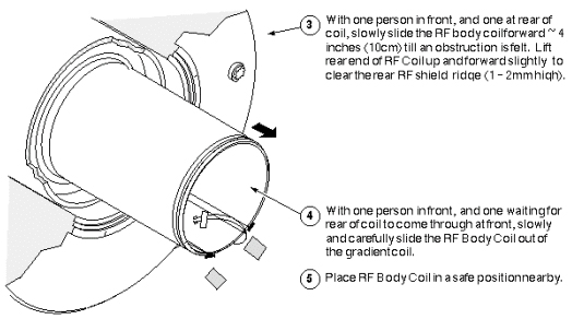
Figure 10. Installing BRM-D (Short) RF Body Coil
Figure 11. Installing the BRM-D (Short ) RF Body Coil
Figure 12. Positioning the BRM-D RF Body Coil
Figure 13. Installing the RF Constraints (Additional Detail)
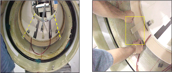
Figure 14. Securing BRM-D (Short) RF Body Coil
- Complete remaining installation steps per Gradient Coil Installation Procedure.
- Return the failed RF coil to the shipping crate, reversing the steps used to remove the replacement coil in Unpacking BRM-D (Short) RF Body Coil.
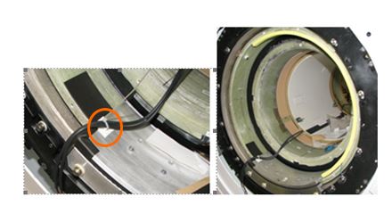
- Route RF cable along left side of the plate, securing in position
using cable mounts (PN 46-208747P1) and cable ties (PN 46-252283P68)
on front support plate.
Figure 15. Route RF cable
- Connect the RF cable J3/J4 which is coming up from body coil
to cable 2018/2019( D-D bias cable) which is coming up from under
the magnet.
Figure 16. RF cable Connection
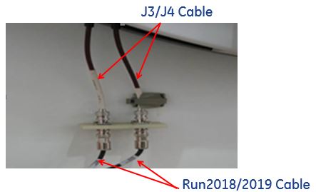 note:
note:Do not have a loop or slack when connecting the D-D bias cable to the body coil cable.
3 Finalization
Procedure
- Install all removed components.
- Clean up the site in preparation for patient scans.
- Perform TR Dynamic Disable Calibration.