Gradient Coil Replacement Preparation
Prerequisites
Procedure
- Remove the Tube and the two Tube Guide Roller Assemblies from
the defective Gradient coil and install one onto each end of the new
Gradient Coil Assembly. note:
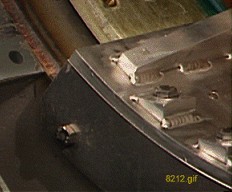
Do not reuse the mounting brackets with gussets. See Figure 1.
Figure 1. Gradient Brackets with Gussets
- On the new gradient, do the following:
- Clean all mounting locations clear of debris (threaded and unthreaded).
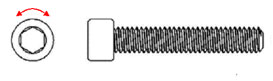
- Clean the bolt threads by using a tack cloth to perform a back
forth motion clockwise/counterclockwise around the threads as shown
in Figure 2. Ensure any loose debris in the bolt threads is removed.
Figure 2. Bolt Cleaning Procedure
- Clean underside of BRM bracket (2213168-3) by using a tack cloth
as shown in Figure 3. Make sure that the underside of the bracket is free of any metallic
particles.
Figure 3. BRM Support Bracket Cleaning Procedure
- Install front support assembly (2213168-3) to front of gradient coil using four M10x40 screws (2174921-25), washers (2184009) and two drops of Loctite #242 (p/n 46-170686P3). Torque the M10x40 screws by hand so they are snug, then 1/2 turn to properly tighten.
- Put on disposable protective gloves.
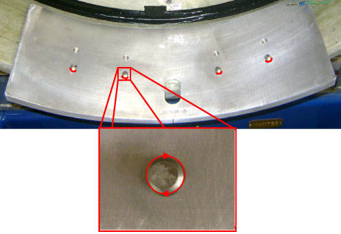
- If the BRM bracket only uses 4 bolts then fill the 4 unused
bolt holes with caulk as shown in Figure 4. Wipe away excess
caulk so that the caulk is flush with the bracket’s surface
as shown in Figure 5.
Figure 4. Unused Bolt Hole Caulking Locations (if applicable)
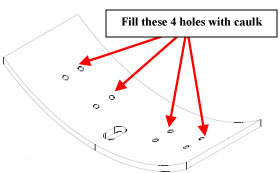
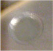
Figure 5. Close-up of Unused Bolt Hole Filled with Caulk
- Apply caulk to the periphery of the bracket as shown in Figure 6 by applying caulk
to the tip of your finger and then running your finger along appropriate
mating surfaces (use approximately 1/8 in. fillet of caulk). Dotted
lines represent edges that are not visible from this view. Reapply
caulk to your finger as needed. Figure 7 (semi-circle), Figure 8 (front edge), Figure 9 (left edge), Figure 10 (back edge) and Figure 11 (right edge)
provide a more distinct view of each of the mechanical barriers that
are to be sealed with the caulk.
Figure 6. Bracket Periphery Caulking Procedure
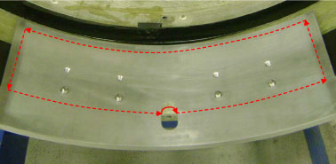
Figure 7. Semi-circle Caulk Application
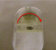
Figure 8. Front Edge Caulk Application
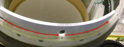
Figure 9. Left Edge Caulk Application
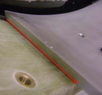
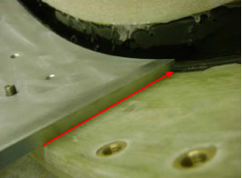
Figure 10. Back Edge Caulk Application (Apply caulk to the bottom edge where the BRM bracket and gradient surface meet)
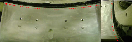
Figure 11. Right Edge Caulk Application
- Apply a small amount of caulk to the periphery of the threaded
bolts as shown in Figure 12. The process is the same whether 4 or 8 bolts
are used for the application.
Figure 12. Threaded Bolt Caulk Application
- Allow caulk to cure naturally.
- Install rear support (2213167-3) to the rear of the gradient
in the same manner.note:
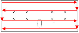
There are 8 screws for each bracket. If the gradient has 8 holes, use 8 screws; if the gradient has 4 holes, use only 4 holes of the 8 holes on the bracket, as shown in Figure 13.
note:The old brackets in the WideOpen Enclosure differ from the new brackets. See Figure 13.
Figure 13. Gradient Brackets Installation
- Remove the shipping blocks from the new Gradient Coil and cradle.
- Remove the Gradient Coil roller assemblies from the defective Gradient coil and install onto the front end of the new Gradient coil.
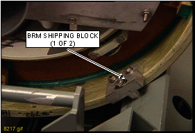
- Install the shipping blocks onto the defect Gradient coil cradle,
one on each end. See Figure 14.
Figure 14. Install Gradient Coil Shipping Blocks
 note:
note:Lift the defective Gradient coil and cradle from the cart using a fork lift or other lifting method that is capable of lifting 4000 lbs (1815 kg), and place on the ground. Lift the new Gradient Coil and cradle onto the cart using the same method.
- Wash the threaded holes on the end flange of the magnet with alcohol to make it ready for the mounting bracket.
Finalization
No finalization steps.